Acromag EIS-358 User Manual Download Page 8

2-4 

Connecting to Input Power 

IMPORTANT:

 Turn off input power and unplug the power terminal block before making wire 

connections. Otherwise, your screwdriver blade can inadvertently short the terminal connections 
to the grounded enclosure. 

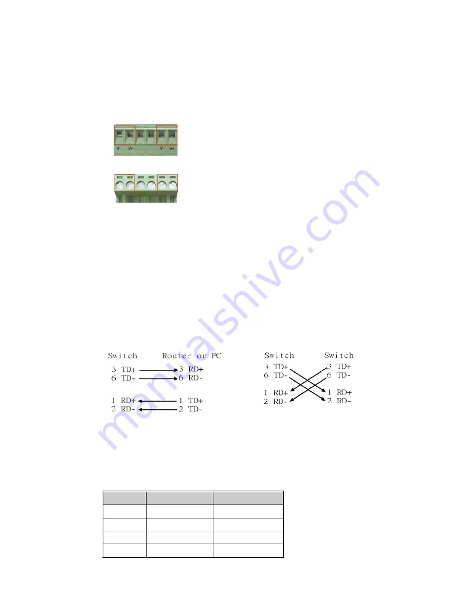
1.  Insert the positive and negative wires of your DC supply into the V+ and V- contacts of the 

terminal block connector.    The acceptable wire range is 12 to 24 AWG.     


2.  Tighten the terminal screws to prevent the wires from coming loose. 


3. 

OPTIONAL – DC IN:

 This switch has an additional power jack for the connection of AC-DC 

power converters (wall-transformer type), like those used in SOHO (Small Office/Home 
Office) applications. Be sure that the adapter output voltage remains within the required 
12-48V DC range under load and is of sufficient capacity to power the unit. Refer to the 
switch PWR LED to verify power via this jack. If a power supply is connected to all three 
input power terminals, the switch will be powered from the highest voltage level. 

Connecting to the Ethernet Ports 

This switch includes eight RJ-45 ports with automatic MDI/MDI-X cross-over, and automatic 
10/100Mbps data rate sensing for 10Base-T or 100Base-TX connections. Automatic MDI/MDI-X 
crossover allows you to connect to other switches, hubs, or workstations, without regard to using 
straight-through or crossover cabling. The following figures depict the schematic diagram of 
straight-through and crossover cabling. Note that crossover cables simply cross connect the 
transmit lines at each end to the receive lines at the opposite end. 


Straight-through Cabling Schematic 

Crossover Cabling Schematic 


All ports of this switch support automatic MDI/MDI-X. When you use an Ethernet cable to 
connect to other devices (computers, switches, or hubs), pins 1, 2, 3, and 6 of the 8-pin RJ45 
connector are used to transfer signals between connected devices, and the signals of these pins 
are automatically crossed by the MDI-X function as shown in the table below. 


Pin MDI-X 

Signals 

MDI Signals 

1 RD+  TD+ 

2 RD- 

TD- 

3 TD+  RD+ 

6 TD- 

RD- 

Summary of Contents for EIS-358

Page 1: ...thernet Rail Switch User s Manual ACROMAG INCORPORATED Tel 248 624 1541 30765 South Wixom Road Fax 248 624 9234 P O BOX 437 Wixom MI 48393 7037 U S A Copyright 2005 Acromag Inc Printed in the USA Data...

Page 2: ...ng to Input Power 2 4 Connecting to the Ethernet Ports 2 4 Connecting to the Alarm Output Relay 2 5 Cabling 2 5 DIN Rail Mounting Installation 2 6 Wall Mounting Installation 2 7 Setting Up a Redundant...

Page 3: ...n one port is received by the same switch at another port two message paths exist This switch is smart enough to temporarily disable the second path holding it as a backup in case the primary path fai...

Page 4: ...switch One DIN Rail clip attached to the switch One wall mounting plate with six screws separate accessory User s manual CD ROM Quick Installation Guide If any of the above items is missing or damaged...

Page 5: ...ches LED Indicators Connecting to Input Power Connecting to the Ethernet Ports Connecting to the Alarm Output Relay Cabling DIN Rail Mounting Installation Wall Mounting Installation Introduction Panel...

Page 6: ...ort alarms and to designate the switch as Ring Master for redundant ring applications The default setting of these switches is OFF DIP Switch No Status Description OFF Disable the corresponding port a...

Page 7: ...ant media ring at ports 7 and 8 see DIP switch 9 R M Ring Master OFF This switch is NOT the Ring Master in a redundant media ring Green A network device is detected Blinking Green The port is transmit...

Page 8: ...power terminals the switch will be powered from the highest voltage level Connecting to the Ethernet Ports This switch includes eight RJ 45 ports with automatic MDI MDI X cross over and automatic 10...

Page 9: ...ontacts are energized open circuited for normal operation and close for fault conditions This contact does not supply any power and is rated up to 24V DC at 1A 1 Wire this alarm switch per your applic...

Page 10: ...lip is positioned at the top 2 For surface or wall mounting you can remove the DIN Rail clip in similar fashion Follow these steps to mount the switch to the DIN Rail track 1 Insert the upper end spri...

Page 11: ...e have the same redundant ring method Only one switch should be set to Ring Master When you complete a media loop the Ring Master switch will automatically sense the presence of the loop disable the s...

Page 12: ...to wire the power input Refer to Connecting to Alarm Output Relay for an information on how to wire to the relay 5 The PWR1 and PWR2 power inputs can be connected to power sources simultaneously When...

Page 13: ...sfully established 10 Turn on Power to the host activate the Windows Command Line mode and ping a connected Ethernet device to see if it will respond 11 To enable the Windows Command Line Mode click o...

Page 14: ...network using switches Note that Computer A needs to connect to several modems simultaneously to provide network access to many users However Computer A does not have additional COM ports to connect a...

Page 15: ...serial converters Upgrading Firmware The switch makes use of the Trivial File Transfer Protocol TFTP to transfer files between a network host and the switch in order to upgrade its firmware IMPORTANT...

Page 16: ...STP types Shielded cables are recommended In general category 3 4 and 5 Ethernet cables are suitable for systems with 10Mbps transmission speed But for systems at 100Mbps you should only use Category...

Page 17: ...sted pair UTP STP Cat 5 cable EIA TIA 568 100 ohm 100 meters maximum length Back plane 1 6Gbps Throughput 1 19Mpps with 64 bytes packet and 8 active ports Power Supply 12 to 48 VDC redundant dual DC p...

Reviews: