


INDUSTRIAL I/O PACK SERIES APC8640 PCI BUS CARRIER BOARD
_________________________________________________________________________________________________________________
- 8 -
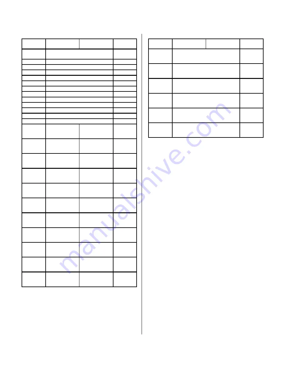
Table 3.3: APC8640 Carrier Board Memory Map
P
(Hex)
High Byte
D15 D08
Low Byte
D07 D00
P
(Hex)
0001
Carrier Board Status / Control
Register
0000
0003
IP Interrupt Pending Register
0002
0005
IP A Interrupt 0 Select Space
0004
0007
IP A Interrupt 1 Select Space
0006
0009
IP B Interrupt 0 Select Space
0008
000B
IP B Interrupt 1 Select Space
000A
000D
IP C Interrupt 0 Select Space
000C
000F
IP C Interrupt 1 Select Space
000E
0011
IP D Interrupt 0 Select Space
0010
0013
IP D Interrupt 1 Select Space
0012
0015
IP E Interrupt 0 Select Space
0014
0017
IP E Interrupt 1 Select Space
0016
0019
Clock Control Register
0018
001B
↓
003F
Not Used
1
Not Used
1
001A
↓
003E
0041
↓
007F
IP A
ID Space
IP A
ID Space
0040
↓
007E
0081
↓
00BF
IP B
ID Space
IP B
ID Space
0080
↓
00BE
00C1
↓
00FF
IP C
ID Space
IP C
ID Space
00C0
↓
00FE
0101
↓
013F
IP D
ID Space
IP D
ID Space
0100
↓
013E
0141
↓
017F
IP E
ID Space
IP E
ID Space
0140
↓
017E
0181
↓
01FF
IP A
I/O Space
IP A
I/O Space
0180
↓
01FE
0201
↓
027F
IP B
I/O Space
IP B
I/O Space
0200
↓
027E
0281
↓
02FF
IP C
I/O Space
IP C
I/O Space
0280
↓
02FE
0301
↓
037F
IP D
I/O Space
IP D
I/O Space
0300
↓
037E
0381
↓
03FF
IP E
I/O Space
IP E
I/O Space
0380
↓
03FE
1. The board will return “0” for all address that are not used.
Table 3.3: APC8640 Carrier Board Memory Map
P
(Hex)
High Byte
D15 D08
Low Byte
D07 D00
(Hex)
0000001
↓
07FFFFF
IP A
Memory Space
0000000
↓
07FFFFE
0800001
↓
0FFFFFF
IP B
Memory Space
0800000
↓
0FFFFFE
1000001
↓
17FFFFF
IP C
Memory Space
1000000
↓
17FFFFE
1800001
↓
1FFFFFF
IP D
Memory Space
1800000
↓
1FFFFFE
2000001
↓
27FFFFF
IP E
Memory Space
2000000
↓
27FFFFE
2800001
↓
3FFFFFF
Not Used
1
2800000
↓
3FFFFFE
Note: Shaded areas not used by APC8621A carrier.
1. The board will return “0” for all address that are not used.
The APC8640 base addresses are determined through the
PCI Configuration Registers. The addresses given in the
memory map are relative to the base addresses (PCIBar2,
PCIBar3) of the APC8640 carrier as shown in Table 3.2. The
addresses within each IP’s own space are specific to that IP
module. Refer to the IP module’s User Manual for information
relating to the IP specific addressing.
The Carrier registers, IP Identification (ID) spaces, IP
Input/Output (IO), IP Interrupt spaces, and Memory (MEM)
spaces are accessible via the PCI bus space as given in Tables
3.3. A 32-bit PCI bus access will result in two 16-bit accesses to
the IP module. A 16-bit or 8-bit PCI bus access results in a
single 16-bit or 8-bit access to the IP module respectively.
Carrier Status/Control Register - (Read/Write, P 00H)
The Carrier Board Status Register reflects and controls
functions globally on the carrier board. This includes monitoring
the IP Error signal, enabling, disabling, or monitoring IP and
timeout interrupts, performing a software reset including the
carrier and IP modules, and identifying if memory space is
enabled.


