background image

b)  Region Settings  


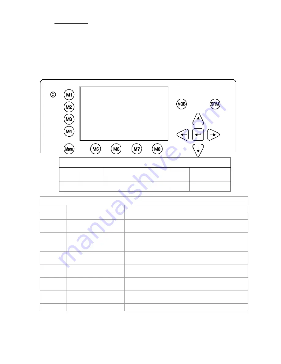
A Region is a defined area, with specific VHF parameters, which are sent out by Vessel Traffic 

Service Stations (VTS), and received via Digital Selective Calling (DSC) or AIS.  


The screen shows a list of Regions, and their input sources. When the vessel enters into one of the 

pre-defined Regions, the NAUTICAST™ automatically switches to the relevant Region Setting. If a 

Region Number is vacant, then the relevant Region Name Slot is currently unoccupied. 


Tip

:

 For fast Region Selection, press the Region Number on the keyboard and the selected region is 

immediately displayed. 


Dynamic Keys: Region Settings


[M5]     [Select]

  Confirm Region 

Number Selection 

[M8]     [Back] 

Return to Menu  

Configuration 

[M6]     [New]


Create New Region 


Overview of Region Settings 

Name 

Region Number 

Number of pre-defined Region 

Valid 

OK 

Status of Region Setting - OK: Stored and Valid 

Source 

A:AddrChM 

A: Addressed Channel Management (Msge. 22)  
Source: VTS via AIS 


B:BcastChM 

B: Broadcast Channel Management 
(Msge. 22) 
Source: VTS via AIS 


C:AIS_ChAs 

C: AIS Channel Assignment Sentence 
Source: Manual ECDIS Input 


D:DSC_Ch70 

D: Channel 70 Telecommand 
Source: Digital Selective Calling 


M:OpManual 

M: Operator Manual Input 
Source: Via  Display 

DaysOld 

Period of time Region Setting is 

stored 

Days, hours, minutes, seconds  
(dd  hh:mm:ss) 

In use 

Region 6 

Region Setting of vessel current operation 

N 1

o

18' E  0

o

12' |1>0.10|2>1.30|3>1.80nm 

*********** Region Settings ************ 

..Name....Valid...Source.......DaysOld.. 

1>Region 1  OK  A:AddrChM     2 06:21:59 

2>Region 2  OK  B:BcastChM   37 09:36:14 

3>Region 3                               

4>Region 4  OK  ?   N/A          N/A     

5>Region 5  OK  M:OpManual   23 11:02:40 

6>Region 6  OK  C:AIS_ChAs   10 12:39:17 

7>Region 7                               

8>Region 8  OK  D:DSC_Ch70   27 05:56:34 

9>Region 9  OK  C:AIS_ChAs    9 17:08:46 


In use:Region 6                          

---------------------------------------- 

NUM| Select->|   New   |         |<-Back 

Y1-03-0203 Rev. M

51

Summary of Contents for Nauticast 2607

Page 1: ......

Page 2: ...le for any specific indirect incidental or consequential damages as a result of its use ACR components may only be used in safety of life devices or systems with the express written approval of ACR as...

Page 3: ...ice Password Protected 23 3 4 7 Display Settings 24 3 4 8 Graphical Display Settings 24 3 5 Sub Menus Detailed 24 3 5 1 Messages 24 3 5 2 AIS Status 36 3 5 3 Voyage Settings User Password Protected 40...

Page 4: ...H Released Editorial work B Werner A Lesch 2005 11 21 1 0 5 I Released Position pinning A Lesch 2006 05 23 1 0 6 J Released Editorial work M D Arcangelo 2006 11 06 1 0 7 K Released Updated AIS Menu s...

Page 5: ...s Data After initial entry of the Ship Settings Data any changes in the information below should be edited accordingly See section 1 3 on entering information Enter Call Sign Enter Ships Name Enter Le...

Page 6: ...umber is available use the value 0 Zero Service Configuration Menu Example Note MMSI and IMO Data input are limited to 9 characters N 1o 21 E 0o 14 1 0 01 2 1 30 3 1 80nm 6 Service Configuration 1 Cha...

Page 7: ...nd enter a default ShipType with the Left Right arrows Setting the Internal and External GPS Antenna Position Note It is critical for the proper orientation of your ship to other AIS users to enter th...

Page 8: ...board right side Your reference points must match the entered ship dimensions Length of ship 220m and Beam 43m For incorrect dimension the AIS shows ext int ship len beam don t match After correct set...

Page 9: ...d the unit would have to be returned to the ACR Service centre This service is not free of charge Once you have entered the system please change the default password to your own passwords for both lev...

Page 10: ...ct Submenu 1 Change Service Password with cursor button Up Down by pressing Number 1 on the keyboard Service Menu Example N48 12 E 16 26 1 N A 2 N A 3 N Anm 6 Service Configuration 1 Change Service Pa...

Page 11: ...r Password Settings with cursor button Up Down by pressing number 2 on the keyboard Select Submenu 1 Change User Password with cursor button Up Down by pressing Number 1 on the keyboard N48 12 E 16 26...

Page 12: ...em Repeat the new Password Press Save to store the changes N48 12 E 16 26 1 N A 2 N A 3 N A Change User Password Enter new password Repeat new password Length 6 8 character Enter Back N48 12 E 16 26 1...

Page 13: ...User Interface Soft Keys M1 M8 Display Safety Keys Cursor Cross Enter Key Keyboard Navigation Screen Header max 3 lines _________________ Navigation Screen or MENU Structure Content 13 lines Y1 03 02...

Page 14: ...navigation within the current screen Up Down Left Right In addition to the actually displayed Enter button the center of the cursor cross always has the Enter functionality 2 3 Explanation of the Num...

Page 15: ...isplay Settings Brightness and Contrast Regulator This Soft Key allows the Display Settings to be changed between Daytime and Nighttime Modes Menu Go to Main Menu or return to the Navigation View Scre...

Page 16: ...se Over Ground Heading Date and the UTC After line 4 all data refers to other vessels within receiving range Dynamic Keys Navigation Screen M5 Select desired vessel for Vessel Details Up Down Scroll V...

Page 17: ...rue Heading Reg Indicates the actual region of own vessel s position If no region number is displayed then the vessel is traveling on high sea and is outside a predefined region Message SRM Indication...

Page 18: ...the Vessel Listing By pressing the Right key it is possible to scroll to the next page for further Vessel Listing by pressing the Left the user scrolls back to the previous page Further details on an...

Page 19: ...ition of the selected vessel LAT S74 50 231 LON W 9o 34 192 Heading and Rotation of the selected vessel Heading 77o ROT 0 2o min l IMO Number and MMSI of the selected vessel IMO No 90733283 MMSI 5004...

Page 20: ...0 15 12 31 NavSt Moored Information on the vessel s Equipment Position Finding Device EPFDType GPS Position Accuracy and Data Terminal Equipment DTE PosAcc High 10m DTE Available This information indi...

Page 21: ...ated within closest range of the own ship Tip Fast Menu Selection is achieved by simply pressing the desired Submenu Number on the keyboard 3 3 Main Menu Note The Navigation Screen automatically appea...

Page 22: ...tory 5 Inbox SRM 6 Inbox LRI Msg 7 Inbox Lock Reply 8 Interrogate IFM Displ NUM Select Back N 1o 18 E 0o 12 1 N A 2 0 00 3 0 10nm 2 AIS Status 1 State Conditions View 2 Own Ship Data 3 Own VHF Status...

Page 23: ...D Ship Type Cargo ship DATA OK PRESS M5 TO SAVE DATA Save Back N 1o 21 E 0o 14 1 0 10 2 1 30 3 1 80nm 5 Transponder Configuration 1 Change User Password View 2 Region Settings 3 Alarm Settings 4 Inter...

Page 24: ...ess 3 Contrast 2 NUM DayNight Back N48 12 E 16 26 1 N A 2 N A 3 N An 1 Messages 1 Write Addressed SRM View 2 Write Broadcast SRM 3 Inbox History 4 Inbox SRM 5 Inbox LRI Msg Displ NUM Select Back N 1o...

Page 25: ...re automatically deleted when the respective Inbox has reached its maximum storage capacity Message Type Maximum Storage Capacity Addressed or Broadcast Messages SRM Latest 30 Messages stored Alarms A...

Page 26: ...he same addressee A second activation of the Back button leads to the Vessel Listing and allows selection of another addressee It is possible to select the desired channel by pressing the Channel butt...

Page 27: ...e immediately due to Transponder in operation In this case the confirmation of the send message arrives later upon Transponder re operation Successful Message Confirmation late reply LAT N 1o 18 963 E...

Page 28: ...ossible by pressing the Send button The Back button leads to the Message Editor It is possible to select the desired channel by pressing the Channel buttons The default Settings for Broadcasted Messag...

Page 29: ...isting with the option of further Message Writing to individual vessels In the case of failed transmission the following screen appears In this case it is recommended to retransmit the Broadcast Messa...

Page 30: ...LRI is automatically dealt with and own vessel data is sent Manual Mode The LRI needs to be manually handled NOTE The data which may be interrogated via the Long Range Interface can be configured in...

Page 31: ...g place when the transponder is set in automatic mode Upon pressing the Reply button user returns to the Message Editor from where it is possible to send an addressed message to the LRI sender An LRI...

Page 32: ...w screen To select a message navigate with the cursor Up or Down the selected message text is displayed in the text field The Back button takes the user to Messages Menu N 1o 20 E 0o 14 1 0 10 2 1 30...

Page 33: ...voked alarm no longer active ACK Acknowledged Abbreviation which is displayed on bottom right hand corner and signifies that selected message or alarm has been previously acknowledged Inbox History Me...

Page 34: ...3 38 general failure 6 Alarm new and valid with ID Number 6 not yet revoked at 13 38 with text general failure ALR 13 39 no sensor pos in use26 Alarm old still valid and requiring attention with ID Nu...

Page 35: ...36 Date 11 26 mm dd POS 01 1 Message Type ALARM Alarm ID 30 Status Valid alarm requiring action See also chapter 5 1 for more details about Alarms N48 12 E 16 26 1 N A 2 N A 3 N Anm Inbox History TXT...

Page 36: ...act with the other vessel in the listing Time the Transponder mode Mod the synchronization status Syn and the total number of vessels being received by each vessel in the listing RXVe The vessel s MMS...

Page 37: ...shows own Ship and Voyage Data which was previously input in Menu 3 Ship Settings and Menu 4 Voyage Settings N 1o 26 E 0o 19 1 0 10 2 1 30 3 1 80nm Time 0 08 LAT N 1o 18 901 LON E 0o 12 345 Heading 2...

Page 38: ...tes the type of cargo on board N A or harmless Further Vessel Details Draught 3 3m Dest HAWAII ETA 10 15 12 31 NavSt Moored Information on the vessel s Equipment Position Finding Device EPFDType GPS P...

Page 39: ...standard operation this Log should not contain any entries N48 12 E 16 26 1 N A 2 N A 3 0 00nm Version Info Hardware AIS Transponder Class A R4 J Software 2 0 S105 X309 SW Stamp Mar 25 2009 09 45 59...

Page 40: ...the User Password in Menu 5 Configuration Submenu 1 Change User Password After the Voyage Settings have been input and saved this screen appears Exit takes the user back to the Main Menu Dynamic Keys...

Page 41: ...fined by the IMO ITU R M 1371 page 47 table 18 and correspond to the Type of Ship chosen in the Ship Settings Entries which do not correctly correspond to the Ship Type and Cargo Category Guidelines a...

Page 42: ...anual input Dest Destination Manual input ETA Estimated Time of Arrival ETA Manual input NavSt Navigational Status Default Setting Selection Under way using engine At anchor Not under command Restrict...

Page 43: ...t the protection foil see Appendix 7 2 for password information Before entering Ship Settings for initial NAUTICAST operation it is advised to configure the User Password in Menu 5 Configuration Subme...

Page 44: ...points for GPS antenna Manual input Ship Type Ship Type according to IMO Regulations Default Setting Selection N A or no ship WIG Vessel Vessel Fishing Vessel Towing Vessel Tow 200mbreadth 25m Vessel...

Page 45: ...lowing dimensions Length 220m Beam 43m Input A 200 then press Enter or B 20 then press Enter C 10 then press Enter D 33 then press Enter Result The NAUTICAST automatically calculates A B and C D and s...

Page 46: ...30m Setting of the internal GPS antenna position A 171m the distance from bow to the antenna B 29m the distance from the antenna to the stern C 0m the distance from the port side to the antenna D 30m...

Page 47: ...rmation Dynamic Keys Transponder Configuration M5 Select Select desired Submenu M8 Back Return to Main Menu N 1o 33 E 0o 26 1 01 10 2 1 30 1A1L 5 Transponder Configuration 1 Change User Password View...

Page 48: ...Exit Return to Vessel Listing Incorrect User Password Input If the incorrect User Password is input the screen below appears Dynamic Keys User Password Input Access Denied M8 Exit Return to Vessel Lis...

Page 49: ...generate them Dynamic Keys Initial User Password Setting M5 Enter Confirm User Password Input M8 Back Return to Menu Configuration N 1o 19 E 0o 12 1 0 10 2 1 30 3 1 80nm 5 Configuration 1 Change User...

Page 50: ...h the New and Repeated User Passwords again Exit takes the user back to the User Password Input Screen Dynamic Keys User Password Input Password Mismatched M8 Exit Return to Password Input Screen The...

Page 51: ...er of pre defined Region Valid OK Status of Region Setting OK Stored and Valid Source A AddrChM A Addressed Channel Management Msge 22 Source VTS via AIS B BcastChM B Broadcast Channel Management Msge...

Page 52: ...minutes TrZone 3 Transitional Zone Size Selection Nautical Miles ChannAIS1 Primary AIS Channel Manual Input Channel Number BandwAIS1 Bandwidth for Primary AIS Channel Selection Default Setting as def...

Page 53: ...r modes of response to Long Range Interrogation Requests LRI It is possible to set the AIS station to respond automatically or manually to LR Interrogations and determine which vessel data may be inte...

Page 54: ...ages Submenu 6 Inbox LRI where the request can be read and replied to LAT N 1o 20 261 ExtSOG 34 6kn 1L LON E 0o 13 705 IntCOG 173 0o 13 37 34 IntGPS 3D ExtHDT 222o Reg6 B 001 021 ShipName RNG BRG SOG...

Page 55: ...4800 9600 38400 baud Monitor the connected sensor inputs for each sensor channel Verify and edit the Sensor Configuration on the display screen Analyze the information received from the connected sen...

Page 56: ...le is installed Please mention the system will restart automatically when saving these setting later Pos Pinning The screen provides means to switch the position pinning function of the internal GPS r...

Page 57: ...he protection foil see Appendix 0 for password information Dynamic Keys Service Configuration M5 Select Confirm Submenu Selection Enter Confirm Submenu Selection M8 Back Return to Main Menu After ente...

Page 58: ...Password configuration see Menu 5 Configuration Submenu 1 Change User Password Dynamic Keys Change Service Password M5 Enter Confirm New Service Password Input M8 Back Return to Submenu Service Config...

Page 59: ...nge User Password Protection M5 Save Save User Password Setting Enter Save User Password Setting M6 Change Configure Password Setting on off Right Left Configure Password Setting on off M8 Back Return...

Page 60: ...gate Data Input Fields up down d Restore Factory Settings CAUTION By acknowledging the return to Factory Settings Command all previous settings both the User and Service Passwords and all manually inp...

Page 61: ...possible to adjust the Brightness and Contrast Settings for both Display Settings The maximum setting for Brightness and Contrast is 9 the minimum setting is 0 It is possible to automatically switch t...

Page 62: ...ant information source The GUI is only visible in the advanced version of the NAUTICAST software version 2 0 1 0 or higher NOTE The Automatic Identification System AIS provides additional information...

Page 63: ...ects the Main Menu FN Up Down Changes the Zoom Level Shift Up Down Scrolls the view only in radar view available 3 6 1 Switching between the Views Navigation Screen LAT N 1o 27 845 ExtSOG 34 6kn 05 26...

Page 64: ...pressing M2 leads to Radar View pressing M2 leads to Fairway View pressing M2 leads you back to Navigation Screen 64 Y1 03 0203 Rev M...

Page 65: ...d description see later chapter Error Reference source not ound AIS Targets Other AIS Targets received within VHF range are displayed as long as they fit in the current zoom level They are displayed a...

Page 66: ...the view only available in radar view Zoom Levels To adjust the Radar View following zoom levels are implemented default is zoom level 4 ZOOM LEVEL Radius 1 2 3 4 5 6 7 8 Outer Ring nm 0 3 0 6 1 5 3 7...

Page 67: ...ter distance ring in the current zoom level The view can be scrolled by 2 steps in each direction The view can be scrolled by pressing Shift Up to scroll towards North and Shift Down to scroll towards...

Page 68: ...list shows the same targets as shown in the Navigation Screen Ship List Minimized View Switch This switch indicates whether targets can be selected from the Ship List or from the minimized view If the...

Page 69: ...isplayed instead of the minimized view Pressing Up or Down scrolls the ship detail list by line Left or Right by page M8 returns to the minimized view 3 6 3 The Fairway View The Fairway View shows the...

Page 70: ...er option on AIS targets M2 Switch between the views M3 Show alarm windows M5 Acknowledge alarms or safety related messages SRM M7 Acknowledge SRM and reply Menu Select the Main Menu Up Down Left Righ...

Page 71: ...side a Ship List is displayed and on the right hand side a minimized Fairway View is seen This view is displayed if one of the cursor keys is pressed Fairway View Up Down Left Right Minimized Fairway...

Page 72: ...t targets can be selected from the minimized view with the Up or Down or Left or Right buttons Regardless on which side of the screen targets are selected both views correspond to each other Minimized...

Page 73: ...view in the big views as well as minimized views and ship details list Alarms can be set to be displayed in the foreground or minimized Refer to chapter 3 6 5 Configuration of the Graphical Display f...

Page 74: ...ynamic Keys Main Menu Screen M5 Select Select chosen Submenu Enter or Right Confirm Submenu Selection M8 Back Return to Navigation Screen Up Down Navigate Submenu for selection N 1o 46 E 0o 39 1 0 10...

Page 75: ...Graphical Settings AIS target filter settings enabling disabling the Auto Zoom feature Alarm appearance Fairway View Scale Dynamic Keys Fairway View Scale M5 Save Save the settings M8 Back Return to...

Page 76: ...oose a width greater than the visible Zero line you have to enter here 100 additionally the parameter Dim D has to be set to a value greater than zero Value range 10 to 100 Dim D The parameter Dim D d...

Page 77: ...u and additionally presents the transformation process from the Radar View to the Fairway View 10 nm Horizontal line 260 325 0 30 5 nm 15 nm DIM B f1 f 2 Zero line DIM C Dim D f2 0 s Angle A N COG 5 1...

Page 78: ...owing symbols are available Parameter Symbol Standard Standard Vectors Standard Solid Standard Solid Vectors Solid Reduced 3x3 3D Samples Note Other symbols i e for a Base Station are fixed N53 31 E10...

Page 79: ...rd Vectors Standard Solid Standard Solid Vectors Solid Reduced 3x3 Note Other symbols i e for a Base Station are fixed N53 31 E10 1 1 0 69 2 0 77 3 1 08nm Radarview Symbols Radarview Symbols Own Ship...

Page 80: ...Max Count Sets the maximum number of displayed targets For example a max Count of 20 displays 20 closest targets Auto Zoom Is set to on a zoom level is set automatically that the targets fit best int...

Page 81: ...fitted with Safety Keys which allow the user to automatically send urgent messages without the necessity of navigating the Menus The SRM Button sends out Broadcast Safety Related Messages to all ship...

Page 82: ...ent area The at the end of the Vessel Listing indicates that further Vessels are listed and can be scrolled using the Left or Right buttons Dynamic Keys Write Addressed SRM M5 Send Send an Addressed M...

Page 83: ...uld be checked before transmission To confirm message transmission to all vessels within range it is necessary to activate either the Send or SRM button The Back button takes the user back to the Mess...

Page 84: ...is taken back to the Vessel Listing for the option of writing further addressed messages Dynamic Keys Send SRM to Addressed Vessel M5 Select Select Vessel for Messaging M8 Back Return to Submenu Messa...

Page 85: ...y Sending a further SRM to an Addressed Vessel Dynamic Keys Write Addressed SRM M5 Send Send Message M8 Back Return to Vessel Listing M6 Channel Select Transmission Channel M7 Channel Select Transmiss...

Page 86: ...See tables page 41 for Alarm and TXT Messages Select AIS Status with cursor button Up Down or press Nr 2 on the keyboard Select Alarm Status or TXT Status with cursor button Up Down or press Nr 4 or 5...

Page 87: ...r position in use No valid position from internal GPS or external position sensor Reaction The transponder unit continues operation Remedy Check the sensor cabling and the antenna of the internal GPS...

Page 88: ...he internal GNSS receiver is capable of processing DGNSS corrections Remedy no action required 24 AIS internal DGNSS in use message 17 25 AIS internal GNSS in use Information additional to Alarm ID 25...

Page 89: ...Mariahilfer Stra e 50 2 11 A 1070 Vienna Austria Tel 43 1 5 237 237 0 Fax 43 1 5 237 237 150 Email Technical Support acr europe com Web www acr europe com ACR Electronics Customer Service 5757 Ravens...

Page 90: ...ernal Heading True SRM Safety Related Message ExtSOG External Speed Over Ground Syn synchronization GNSS Global Navigation Satellite Service TrZone Transitional Zone GPS Global Positioning System TxA...

Page 91: ......

Page 92: ...woodRoad r r t f FORTLAUDERDALE FL 3331 6645 USA Applicant ACR El ectronicsEutoft GinbFl t 1 1 Address r 2 Tndelskpi 8 1 Top 632 1020MENNA AUSTRIA Address Handelskai 388 Top 632t 1020oVl ENN4 inl A 1l...

Page 93: ...Notes The manufacturershall inform Bundesamt f r Seeschifffahrtund Hydrographie as the notified body of any modifications to the type tested product s that may affect compliance with the requirements...

Page 94: ......

Page 95: ......

Page 96: ......

Page 97: ...nland AIS Edition 1 0 dated 31 5 2007 Diese Erkl rung bescheinigt die bereinstimmung mit den genannten Richtlinien ist jedoch keine Zusicherung von Eigenschaften Die Sicherheitshinweise der mitgeliefe...

Page 98: ...Tracing Systems for Inland Waterways Ed 1 01 dated 10 10 2007 Test Standard for Inland AIS Edition 1 0 dated 31 5 2007 Diese Erkl rung bescheinigt die bereinstimmung mit den genannten Richtlinien ist...

Page 99: ...ed 10 10 2007 Test Standard for Inland AIS Edition 1 0 dated 31 5 2007 Diese Erkl rung bescheinigt die bereinstimmung mit den genannten Richtlinien ist jedoch keine Zusicherung von Eigenschaften Die S...

Page 100: ...f r Verkehrstechniken Weinbergstra e 11 13 56070 Koblenz Germany Spezifizierte Standards Specified Standard s Standard s Sp cifi s IMO MSC 74 69 Annex 3 ITU R M 1371 3 Class A IALA Technical Clarific...

Page 101: ...IS Edition 1 0 dated 31 5 2007 Diese Erkl rung bescheinigt die bereinstimmung mit den genannten Richtlinien ist jedoch keine Zusicherung von Eigenschaften Die Sicherheitshinweise der mitgelieferten Pr...

Reviews: