


24 / Chapter 3 Installation
d.
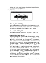
Reset Switch Lead (RST)
This 2-pin connector connects to the case-mounted reset switch
for rebooting your computer without having to turn off your power
switch. This is a preferred method of rebooting in order to pro-
long the life of the system's power supply.
e.
System Power LED (PANEL)
The system power LED lights when the system’s power is on
(same as above Power LED).
f.
Speaker Connector (SPEAKER)
This 4-pin connector connects to the case-mounted speaker.
g.
ATX Power Switch (PW_BN)
The system power is controlled by a momentary switch connected
to this lead. Pushing the button once will switch the system ON.
The system power LED lights when the system's power is on
11.
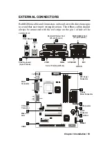
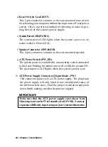
ATX Power Supply Connector (20-pin block) - PW1
This connector connects to a ATX power supply. The plug from
the power supply will only insert in one orientation because of
the different hole sizes. Find the proper orientation and push
down firmly making sure that the pins are aligned.
IMPORTANT:
Make sure that the ATX power supply can take at least
10mAmp load on the 5Volt standby lead (5VSB). You may
experience difficulty in powering on your system without this.


