background image

INSERTING THE ICs

You are now ready to insert the ICs. When you handle the ICs, it is very important that you avoid touching
the pins and that you protect the ICs from static electricity.

1

Remove the ICs from their packaging, holding the IC between finger and thumb.

2

Check that all the pins on the IC are straight. If they appear crooked or splayed, you will need to
realign them. To do this, hold the IC sideways-on and press it gently against a firm flat surface.

3

Repeat for the other row of pins as necessary.

4

Identify socket IC24.

5

Take the IC which you have already identified as ROM 1.

6

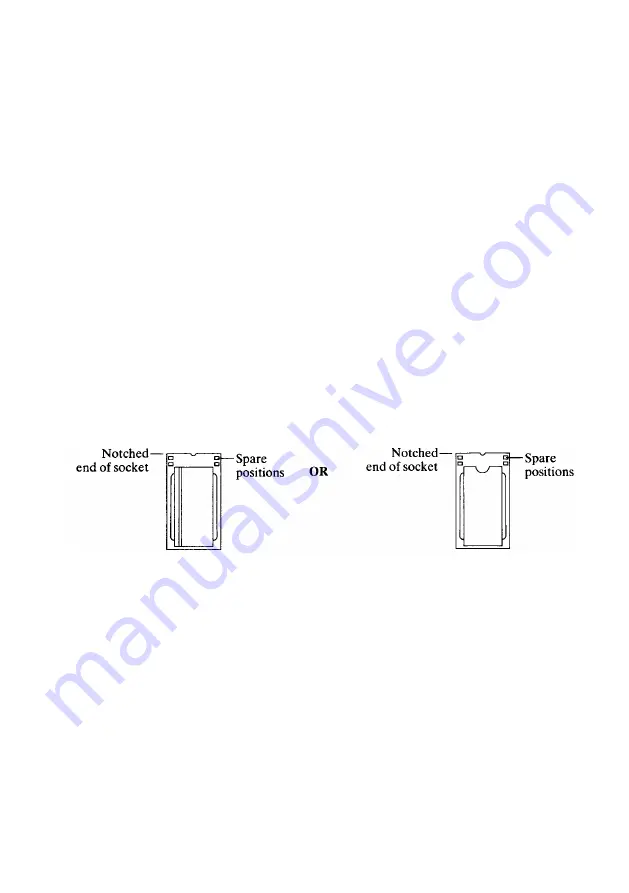
The new ICs each have only 28 pins so four of the pin positions in each of the 32 pin sockets will
be unused. Position the end of the IC with the semi-circular notch towards the notched end of the
socket. (If you have grooved ICs you should position the IC so that the groove is on the
left-hand side of the IC.) In either case, the four free positions should be left at the notched end
of the socket. (See diagram below.)

A 28 pin IC in a 32 pin socket

7

Line up all the pins over socket IC24. Ensure that the notch on the IC points towards the notched
end of the socket (or that the groove is on the left-hand side of the IC).

Also, ensure that you

have left four free pin positions at the notched end of the socket.

8

When you are sure that the IC is the correct way round, apply firm pressure to the IC until you
feel it click home, but do not force it. When the IC is in place it may appear to be slightly raised.

9

Check that all the pins have entered the socket and that none are bent out or caught underneath.

10

Insert the remaining ICs. Ensure that the IC which you have identified as ROM 2 is inserted into

socket IC25, ROM 3 into socket IC26 and ROM 4 into socket IC27.

3

Summary of Contents for Archimedes 300 series

Page 1: ...ers please insert your old 0 2 ROMs into the protective foam which carried your new 1 2 ROM set and return the 0 2 ROMs to Acorn using the envelope and reply paid label provided in this pack This request does not apply to Arthur 0 3 owners REMOVING THE TOP COVER FROM THE COMPUTER CASE 1 Switch off your Archimedes and disconnect the unit from the mains by unplugging the power supply cable 2 Unplug ...

Page 2: ...therwise you may bend the pins or damage the sockets If you are using a screwdriver be careful not to catch the ribs of the sockets IDENTIFYING THE ICs The upgrade kit consists of four ROMs The way in which the ICs are labelled and their appearance depends on the manufacturer Before inserting the ICs it is important to clearly identify the type of ICs you are supplied with Using the table below id...

Page 3: ... end of the socket If you have grooved ICs you should position the IC so that the groove is on the left hand side of the IC In either case the four free positions should be left at the notched end of the socket See diagram below A 28 pin IC in a 32 pin socket 7 Line up all the pins over socket IC24 Ensure that the notch on the IC points towards the notched end of the socket or that the groove is o...

Page 4: ...ug in the mains supply TESTING THE UPGRADE 1 Switch on the monitor 2 Hold down R on the keyboard and switch on your Archimedes 3 If you get a rolling broken picture displayed then switch off your Archimedes and complete step 4 below 4 Hold down R on the keyboard and switch on again After approximately half a second the monitor should display a stable picture of the Desktop The installation is now ...

Page 5: ...red to on page two of the Archimedes Arthur ROM fitting instructions The set is numbered 1 2 3 and 4 and although labelled Arthur 1 1 in fact contains Arthur 1 2 The ROMs are installed in the following sockets ROM 1 in IC24 ROM 2 in IC25 ROM 3 in IC26 ROM 4 in IC27 Refer to the Fitting instructions for information on how to carry out the upgrade Acorn Computers Limited 1987 Published by Acorn Comp...

Page 6: ...Archimedes 300 series PCB showing the position of the four ROM sockets ROM 1 is in socket IC24 ROM 2 is in socket IC25 ROM 3 is in socket IC26 ROM 4 is in socket IC27 FRONT OF MACHINE ...

Reviews: