background image

13

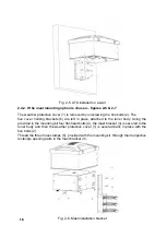
After securing the tuner body (1) on the desk (2) by fastening the bracket bolt (4), the 

bracket (3) remains hidden from sight – figure 2-3. This ensures both a tidy workspace 

and the necessary stability of the tuner body together with up to 5 heavy coaxial cables 

connected to the back side.

WARNING HIGH VOLTAGE

For INDOOR tuner operation, the grounding terminal of the 

tuner labeled GROUND and the antenna feeders should be 

connected as described in S. 1.5.1.

Check if the antenna cables and grounding system of your radio station are installed 

as described in S. 1.5.1. Next, connect the grounding terminal (5) of the tuner labeled 

GROUND (Fig. 2-3) to the 

main grounding plate of the radio station

 (appx.1-9).

After connecting the grounding terminal, connect the antenna feeders (up to 4 coaxial 

cables) to the respective connectors (6) ANTENNA 1 through 4 on the tuner (Fig. 2-3). 

Without powering up the amplifier, use a coaxial cable to connect the tuner HF input (7) 

labeled 50Ohm RF +26 VDC POWER & CONTROL (Fig.2-3) to the ACOM transistor 

amplifiers output labeled RF OUTPUT.

2.4  INSTALLATION AND CONNECTION FOR OUTDOOR OPERATION

The 

wall

 and 

tower

 mounting brackets, provided with your tuner, allow the tuner to be 

remotely mounted, reducing losses, installation costs and installation complexity. This 

option should always be preferred if applicable. Remote operation drastically reduces 

feedline losses, resulting from operating a mismatched coaxial line, leaving only the 

inherent losses of the cable, operated in a source-feedline-load matched mode.

NOTE

For installation and connection for indoor operation see S. 

2.3.

NOTE

Before commencing tuner installation, carefully consider 

and map out the way the coaxial cables run from the ampli

-

fier to the tuner and from the tuner to the antennas, as well 

as the manner in which they will enter the shack.

WARNING HIGH VOLTAGE

To prevent accidents, tuner installation and connection to 

the grounding and antennas should only be carried out in 

clear, quiet and sunny weather

, when there is no danger 

of lightning and static discharges.

Life threatening voltages and electrostatic charges may occur in the antenna and the 

cables you install, both as a result of a direct lightning strike or by induction after a light

-

ning strike on adjacent objects, and may also be statically induced by charged clouds 

or energized by dust storms!

Summary of Contents for ACOM 04AT

Page 1: ...1 ...

Page 2: ...ONNECTION FOR OUTDOOR OPERATION 13 2 5 GROUNDING ADDITIONAL INFORMATION 19 2 5 1 LIGHTNING PROTECTION GROUNDING 19 2 5 2 GROUNDING FOR PROTECTION FROM ELECTRIC SHOCK 19 2 5 3 RADIO FREQUENCY GROUNDING OR COUNTERPOISE 20 2 6 CONNECTING RF CABLES ADDITIONAL INFORMATION 20 3 GETTING STARTED WITH THE ACOM 04AT 21 3 1 TURNING ON AND OFF 21 3 2 INDICATION CONTROLS AND MENUS 22 4 STARTING UP AND MAIN FUN...

Page 3: ...DS 33 6 1 2 SETTING THE TUNING TYPE RATE SHARPNESS SELECTIVITY S R W F 33 6 1 3 EDITING ANTENNA NAMES 33 6 2 MAINTENANCE FUNCTIONS ATU SERVICE MENU 34 6 3 OVERVIEW OF TUNING SETTINGS AND RESOURCES USED 38 6 4 MEASUREMENTS IN THE TUNER ATU MEASURE MENU 39 7 MAINTENANCE 41 7 1 CLEANING 41 7 2 FUSE REPLACEMENT 41 7 3 ACOM 04AT BLOCK DIAGRAM AND PRINCIPLE OF OPERATION 41 7 4 TROUBLESHOOTING MONITORING...

Page 4: ...Provided the SWR of the feedline antenna system is up to 3 1 the tuner can handle input power levels up to 1200W PEP mean or continuous carrier regardless of the operating communication mode For feedline antenna system SWRs between 3 1 and 10 1 the maximum permissible power at the tuner input is gradually reduced down to 200W at SWR 10 1 Table 8 1 allowing for operation within tuner component spec...

Page 5: ...Fax 359 2920 9656 Tel 359 2920 9780 E mail acom acom bg com acom mail orbitel bg or by mail to Sofia Bozhurishte Economic Zone 6 Valeri Petrov str 2227 Bozhurishte Bulgaria Website www acom bg com 1 3 PACKAGE CONTENTS ACOM 04AT tuner complete with Weather Protection Hood ACOM 04 WP three sets of installation accessories ACOM 04 DT desk ACOM 04 WM wall and ACOM 04 MM mast two fuse replacement sets ...

Page 6: ...ls emitted during the tuning cycle Air core coils no magnetic materials and high quality NP0 C0G ceramic capacitors usage throughout the matching circuit Improves harmonic suppression the matching network is a low pass L filter Saves space on the operating position can be located up to 100m 330ft away from the shack Allows remote installation including outdoors close to the antenna feed point mini...

Page 7: ... be connected according to the ap plicable standards and local regulations for electric safety fire safety and lightning protection in all cases the radio station is equipped with outdoor antenna s WARNING HIGH VOLTAGE Never run cables into the radio station directly from outside through a wall or window whether from antennas tun ers groundings telephone or network lines etc The ca bles should fir...

Page 8: ...of the building when coming down from the roof all along the route from the antennas to the foundation of the building where before entering are discharged from the lightning charges in a safe way directly into the ground For this purpose the braids of the coaxial cables should be securely ground ed by a low impedance connection to the main grounding plate of the building Appx 1 8 1 5 1 3 From a l...

Page 9: ...tion driven or buried directly in the ground and in compliance with all requirements of the local standards and regulations for elec tric safety fire safety and lightning protection Appx 1 7 1 5 2 2 The braids of the antenna coax cables should be connected through a low impedance connection preferably flat shaped with a solid cross section of no less than 20 sq mm to the same grounding system for ...

Page 10: ...elements may exceed several thousand volts Never touch the antenna or an tenna isolators during transmission and tuning this may cause deep RF burns as well as indirect traumas such as falling 1 5 4 General Safety Precautions WARNING HIGH VOLTAGE Do not undertake any repair or alteration in the design or software of the tuner by yourself as this may threaten your or someone else s health and life ...

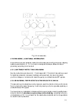
Page 11: ... or water hoses to spray the weather seals or connectors CAUTION Do not try to additional weather sealing to the tuner It should be installed in an airy location in order to cool down during operation and to dry up after rain or morning dew Fig 2 1 ACOM 04AT tuner with the ACOM 04 WP weather protection cover removed and without installation accessories Your new ACOM 04AT will be shipped with the p...

Page 12: ...der as well as for any transpor tation damages If you notice anything missing or damaged immediately notify your ACOM dealer Any delay may void the warranty of the carrier Store safely the unused accessories and entire packing for possible future use or transportation 2 2 POWER SUPPLY VOLTAGE The tuner is powered by direct current voltage 26VDC 10 15 supplied through the coaxial cable from the ACO...

Page 13: ... 4 between the bracket and the tuner body The bracket is finished off with black polymer paint reducing the possibility of ac cidental scratching of the desk surface After mounting and securing the tuner to the desk the only contact surfaces are the rubber feet and rubber protector of the bracket bolt ensuring scratch free desk surface Fig 2 3 Securing the ATU to a desk ...

Page 14: ...ND CONNECTION FOR OUTDOOR OPERATION The wall and tower mounting brackets provided with your tuner allow the tuner to be remotely mounted reducing losses installation costs and installation complexity This option should always be preferred if applicable Remote operation drastically reduces feedline losses resulting from operating a mismatched coaxial line leaving only the inherent losses of the cab...

Page 15: ...all an appropriate set of installation accessories ACOM 04 WM for walls or ACOM 04 MM for masts as described hereafter Do not install the protection cover at this point The tuner should be mounted strictly horizontally with the connectors facing down wards and at a height of no less than 1m above base level ground or roof The installation height above the base is essential in order to install cabl...

Page 16: ...ecessary shielding from the elements whenever it s possible the tuner should be mounted under a shed This way maximum protection and minimum mate rial wear both from water and sunlight and heat will be provided extending the tuner s operational lifespan When installing the system outdoors always select a location free from any possible loose cables or other objects that might fall on or hit the tu...

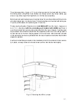
Page 17: ...re left in place attached to the tuner body Using the provided in the mounting kit four flat head bolts 4 the mast bracket 3 is secured to the tuner body and then the weather protective cover 1 is secured back in place with the five bolts 2 Thread the three hose clamps 5 provided with the mounting kit through their respective rectangle opening pairs in the mast bracket 3 Fig 2 6 Mast installation ...

Page 18: ...COM 04 WP over the tuner figures 2 4 to 2 7 1 directing it with the protruding part marked with ACOM up Place it over the provided four carrying pins protruding from the tuner chassis Carefully align the protection hood until the pins fit into the respective holes the cover will go down a bit and will rest on the five carrying plates in the tuner base Check whether all walls of the protection hood...

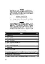
Page 19: ...bles check the reliability of all fixtures and fasten again if necessary Apply mineral jelly or another suitable lubricant to the connectors grounding terminal and assembling nuts and screws to prevent jamming clinching or damage to the threads in a future disassembly LIST OF ACCESSORIES Nr ITEM PCS 1 Mast Bracket 1 2 Desk Bracket 1 3 Cable clamps 5 4 Desk Bracket Bolt 1 5 Desk Bracket Bolt Thread...

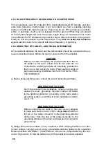
Page 20: ... but does not protect you from voltages or currents with mains frequency or emitted induced RF signals 2 5 2 GROUNDING FOR PROTECTION FROM ELECTRIC SHOCK This grounding or neutralizing in some cases is used for protection from electric shock from currents with mains frequency It will not protect you from a possible lightning or emitted induced RF signals To ensure that your installation complies w...

Page 21: ...to the tuner ensure that its two ends are not connected to anything and take all necessary precautions that no one has access to them Place warning signs at both ends reading WARNING DO NOT TURN ON PEO PLE WORKING a Before doing anything else connect the tuner s grounding terminal WARNING HIGH VOLTAGE Do not proceed with the installation unless you have con nected the tuner grounding terminal mark...

Page 22: ...able and fasten the connector ring 3 GETTING STARTED WITH THE ACOM 04AT CAUTION Never exceed tuner specifications Do not transmit with a high SWR 3 1 TURNING ON AND OFF After you complete the tuner installation instructions verify that the amplifier master power ON OFF switch on the back panel is in the OFF position and the plug is pulled out of the mains socket WARNING HIGH VOLTAGE Before connect...

Page 23: ...e amplifier output Also when the tuner is unassigned you will not be able to use its antenna switch 3 2 INDICATION CONTROLS AND MENUS 3 2 1 TUNER INFORMATION AREA ON THE AMPLIFIER SCREEN After the operator specifies in the USER PREFERENCES that a tuner is installed the amplifier indication changes The screen displays a frequency range showing the availability or absence of tuner settings for all f...

Page 24: ...irection Pressing and holding either of the two buttons for 1s selects the next band in the respective direction Simultaneously pressing the two buttons has no function When there is a CAT interface connected to transceiver the buttons do not appear because the segments and bands are changed via CAT automatically following the transceiver frequency 3 2 3 TUNE BUTTON SECOND FUNCTION BYPASS Pressing...

Page 25: ...ave been assigned the ANT but ton will switch between them in a A2 A4 A2 A4 loop at each button press and the unassigned numbers A1 and A3 in the case will be skipped At each antenna change the frequency segment indication and tuning setting is refreshed as well S 3 2 1 3 2 5 TUNER RELATED MENUS When a tuner is assigned S 4 2 the main menu of the amplifier MENU SELECTION makes available four addit...

Page 26: ...s close to the maximum current or with capacitive hats caps at the maximum voltage across the length of the antenna are normally tuned critically or sharply The higher the degree of physical reduction of the antenna size compared to its full size version the steeper more frequency dependent narrow band and unstable its settings are in comparison with e g the settings of a regular dipole Typical ex...

Page 27: ...Naturally broad band antennas could be declared as WIDE broad band The width of the frequency segments is approximately 4 of the operating frequency This option is convenient for special broad band radiators e g exponential log periodic thick or aperiodic with absorbing loads rhombic etc similar antennas 4 1 4 FIXED An extreme reduction of the physical dimensions of antennas such as for a loop of ...

Page 28: ...matical ly stays in BYPASS mode and the amplifier displays the warning message ATU FULL TUNING REQUIRED If there is a stored setting the tuner reads the relay combination settings from its non volatile memory and immediately performs it by switching all relays in one step and if necessary switches the antenna as well without any emission The amplifier refresh es its indication the new frequency se...

Page 29: ... amplifier end We rec ommend updating the tuning settings with the TUNE button in this case For the purpose of quick tuning without CAT the operator should adhere to the fol lowing rules of operation for frequency and or antenna change Frequency segments can only be changed during reception using the SEG MENT or SEGMENT buttons or by sending a short preliminary transmission Start the main transmis...

Page 30: ...AT or by changing the antenna with the ANT button only if more than one antenna was declared for the operating frequency S 6 1 The last used an tenna is memorized The frequency segment boundaries of validity of the current tuning is numerically indicated on the basic screen of the amplifier above the tuner setting area If the new frequency is outside the current frequency segment a quick tuning wi...

Page 31: ...work With more than 20 RF relays coils and capacitors of various values are added to the circuit or excluded from it Each switching is completed with no RF power to prevent relay contacts from burning For this purpose the tuner has a built in elec tronic switch for local enabling and blocking of the RF power at the required moment synchronously with the algorithm steps while the transceiver power ...

Page 32: ...transceivers with CAT control are used no manu al operations for transceiver control when performing full tuning cycle are required the transceiver even restores the previous operating mode afterwards The operator should only do the following Select the new frequency in receive mode Change the antenna immediately if another antenna is required if there is more than one antenna assigned for the sel...

Page 33: ... scale under the frequency range of the segments The aim is to get the pointer to the center of the scale The proper tuning process starts automatically after the power stabilizes and re mains at approximately 25W Matching cycle is then displayed in front of the nu merical boundaries of the indicated segment The tuning process is completely automated and may continue up to 5s depend ing on the fre...

Page 34: ...be explicitly communicated to the operator A1 SELECTED BY DEFAULT USE ANTENNA ASSIGNMENTS MENU TO CHANGE When the table is empty this message will appear at each new band 6 1 2 SETTING THE TUNING TYPE RATE SHARPNESS SELECTIVITY S R W F The four degrees of selectivity tuning sharpness Sharp Regular Wide or Fixed set the width of the segments in which the user tuning settings will be considered vali...

Page 35: ...n h 6 2 2 ATU STATUS When you select the ATU STATUS function the tuner returns the tuning mode informa tion ATU matched Memory settings ATU in bypass the currently connected antenna number and the boundaries of the current frequency segment 6 2 3 DELETION OF INDIVIDUAL OR GROUPS OF STORED TUNING SETTINGS ERASE CURRENT TUNING erases the tune settings of the current frequency segment from the tuner ...

Page 36: ...you made for various antenna configurations S 6 2 7 NOTE The ACOM04AT tuning memory DUMP LOAD procedures are initiated ONLY from the amplifier ATU Service menu and NOT from the ACOM Terminal S program fig 6 1 Do not use the Firmware Update button for tuning mem ory DUMP as the AMPLIFIER Firmware Update procedure will be initiated instead see the amplifier manual Do NOT change the order of the step...

Page 37: ...s full and the following message is displayed Operation completed successfully i After the download is complete a short beep sound is generated signaling that the Download window can be closed Press the Disconnect button and close the ACOM TERMINAL S program after that j At the selected location on the hard drive a backup file with a bkp as named above can be found containing the dump k Turn OFF t...

Page 38: ... not assigned already S 4 2 The CAT interface connection is not necessary d Call up the ATU Service menu on the amplifier s display S 6 2 e Go to the MEMORY LOAD FROM FILE wait 5 10 min on the amplifier screen and press the SELECT button to confirm the selection f A new UPLOAD window will open in ACOM Terminal S In it click on the BROWSE button and from the drop down menu in the bottom right corne...

Page 39: ... specified by the operator the alert text TUNING OUTDATED is displayed on the amplifier screen but the outdated tuning settings can still be used 6 3 OVERVIEW OF TUNING SETTINGS AND RESOURCES USED When the menu ATU TUNING SETTINGS LOOK UP ERASE is accessed data lines start scrolling the screen for approximately 5s a line per frequency segment with the current operating band and the current operati...

Page 40: ... resource used in the frequency bands for your antennas you can use their changes in the future to determine the stability of the antenna impedance in time thus you can prevent possible failures in an antenna or feeder and you can promptly take precautions to improve the reserve resource before it is too late The ANTENNA or ANTENNA buttons can be used to review the resource table for another anten...

Page 41: ...TENNA VOLTAGE 500V rms ANTENNA CURRENT 10A rms 6 4 2 REFLECTED POWER FORWARD POWER AND SWR AT ANTENNA OUTPUT The reflected power forward power and SWR should not exceed ANTENNA REFLECTED POWER 400W ANTENNA FORWARD POWER 1600W ANTENNA SWR 10 1 Note that at SWR 1 1 at the tuner output the forward power will exceed the tuner input power by the value of the reflected from the output power Therefore it...

Page 42: ...body Fuse F1 should be quick blow fast or flink type labeled F rated for 2A and 250V Littelfuse 0235002 MXP 0235002 HXP COOPER BUSSMANN BK GMA 2 R BK1 GMA 2 R It can be ordered from e g Digi Key F4724 ND F2680 ND BK GMA 2 R BK1 GMA 2 R or from Farnell 1608243 1150650 Fuse F2 should be slow blow antisurge tardy or traege type labeled Т or L rated for 0 8А and 250V Bussmann type S504 800mA It can be...

Page 43: ...s After the matching circuit the RF power passes through the output sensor and the an tenna switch reaching the selected antenna output 1 of 4 The output sensor produc es four analog signals for the output forward and reflected power antenna current and antenna voltage fwda rfla ia and ua The antenna switch is controlled by four relays KA1 to KA4 There is a lightning surge arrestor not shown in th...

Page 44: ...hing circuit towards the target of the tuning i e towards the point 50 j0 Ohm on the complex impedance plane R logic output shows whether the real part of the transformed impedance is above or below 50 Ohm G logic output shows whether the real part of the transformed admittance is above or below 1 50S 20mS PH logic output shows whether the phase sign of the transformed imped ance is inductive or c...

Page 45: ...ith a short pulse of RF power by blocking the MOSFET for a short time and in a few milliseconds reads out the status of the sensors then it blocks the power to the relays by saturating MOSFET again and in this manner switches the relays synchronously with the power and keeps the contacts safely clean S 5 1 Fig 7 1 ACOM 04AT Block Diagram ...

Page 46: ... new relay state is set After waiting a certain amount of time for the relay contacts to settle a new RF pulse follows with sensor reading power included etc until the impedance transformed by the L network enters the range of impedances with SWR 1 3 1 or until the coil and capacitor resource is depleted e g if the SWR of the antenna is too high so no tuning can be found At the end of the tuning p...

Page 47: ...r there is a poor contact or leakage at some connector d If you receive a Timeout Expired message while trying to tune the unit even when the tuning power is increased to 50W and at the same time SWR at the bottom end of the feeder in the radio station is good during tuning this means that The losses at the feeder may be so high that out of the 50W fed under 12W reach the remote unit which is not ...

Page 48: ...sible for antenna SWR above 3 1 the maximum permissible input power is reduced gradually as per Table 8 1 Table 8 1 Maximum input power of the tuner as function of the antenna SWR SWR 1 3 1 3 5 1 4 1 5 1 7 1 10 1 Pin W 1200 900 700 500 300 200 when tuning is possible for SWR above 3 1 WARNING Operation with antenna output SWR above 10 1 is not allowed 8 1 4 RF INPUT CHARACTERISTICS Rated impedance...

Page 49: ...er using a 60kHz 4800bps bidirec tional FSK modem 8 1 10 MAXIMUM LENGTH OF THE INPUT COAXIAL CABLE The maximum length of the RF coaxial cable between the amplifier output and the tuner input S 8 1 4 S 8 1 8 S 8 1 9 S 8 2 9 is 100m 330ft for a cable of RG 213 type or similar The cable characteristic impedance should be 50 Ohm and the DC re sistance should be below 1 Ohm for inner and outer conducto...

Page 50: ...band Regular used by default the width of frequency segments is approximately 1 of the central frequency of the band Wide wide broad band the width of frequency segments is approximately 4 of the central frequency of the band Fixed for the tuning to be valid it requires coincidence of the operating fre quency with tolerance 4 kHz to the stored value 8 2 5 BYPASS AND USE ATU MODES In BYPASS mode al...

Page 51: ...voltage with reverse polarity From excessive RF voltage at the antenna output above 500Vrms From excessive RF current at the antenna output above 10Arms From excessive reflected power at the antenna output above 400W From excessive forward power at the antenna output above 1600W From excessive input power during tuning above 60W From relay switching under RF power hot switching From extreme air te...

Page 52: ...0 000 feet altitude are acceptable 8 3 4 RETURNING TO THE SERVICE PROVIDER NOTE When tuner transportation is required please use the orig inal packaging At first disconnect all cables from the tuner disconnect grounding last Then uninstall the assembly by following the requirements of Sections 2 3 and 2 4 but perform the actions in reverse order Finally pack the assembly and if necessary the insta...

Page 53: ...ALWAYS overcomes the obstacles it can burn destroy or blow up obstacles but lightning charges always reach the ground Lightning strikes cannot be stopped and it is not possible for protected objects to be insulated from them by any means because lightning strikes act as current genera tors with an electromotive force EMF exceeding one billion Volts The only possibility is to capture lightning and ...

Page 54: ...ts along the planned protection paths This can be done by threading ferrite tubes toroids along unfavorable paths i e the cables going to and from the protected object This way the predominant part of the currents will be tapped to the planned protection path i e through the main grounding plate and all wires and cables connected to it and external to the building The latter are intentionally left...

Page 55: ...nce grounding system driven or buried directly in the ground deep enough under the expected frost level of soil in your area and in compliance with all requirements of the local standards and regulations for electric safety fire safety and lightning protection The expected frost level of soil in your area can be obtained from the local electricity company or weather service This is very important ...

Page 56: ...ODUCT SPECIFICA TIONS AND DATAARE SUBJECT TO CHANGE and ACOM reserves the right to make changes and improvements at any time without further notice or obligation to notify any person or organization of such revisions or changes made in order to improve the reliability functions quality design and or performance of ACOM 04AT Further this Operating Manual is provided as is and ACOM shall not be liab...

Page 57: ...2 2 ...
Reviews: