Acnodes RMC8416 Installation Manual Download Page 6

 6

STEP  8.2:  3.5"  DRIVE  INSTALLATION  INTO  THE
SIDE BRACKET

The side bracket supports one 3.5" drive. If you want to
install a 3.5" drive into the side bracket, please follow the
steps below:

Step 1:    Place a 3.5" FDD drive into the bracket. Make
sure the FDD PCB board is facing the surface of the
bracket and the 4-pin power connector and the IDE/SATA
interface connector are facing the rear of the bracket.

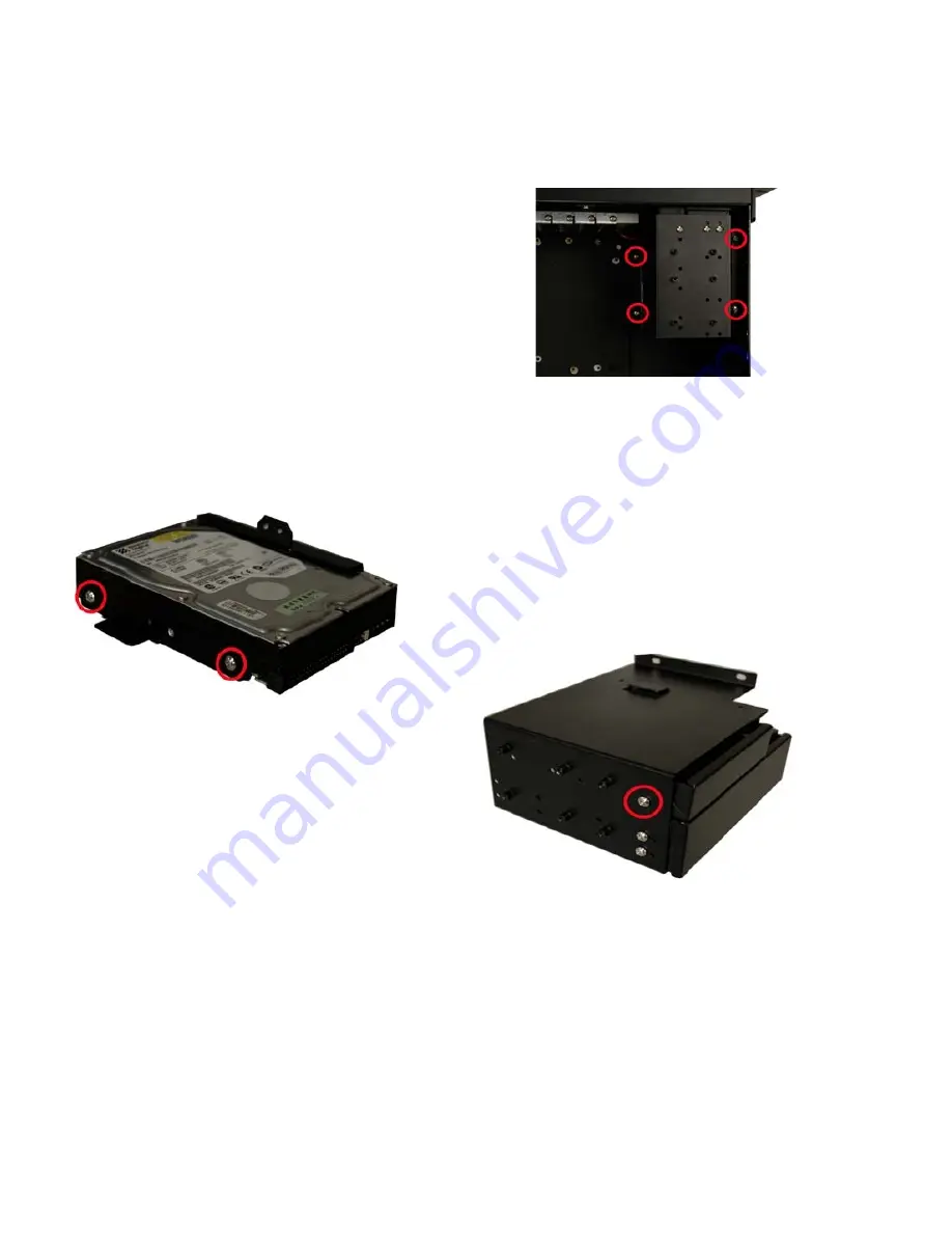
Step 2:    To  secure the  3.5"  HDD  to  the  side  bracket,
insert  4 retention screws, two on each side.

Figure 13: Insert 4 HDD Retention Screws

STEP 8.3: REMOVE THE MAIN DRIVE BRACKET

If you wish to install a 5.25" optical drive or more than one
3.5" drive (HDD or FDD), the main drive bracket must be
removed. To remove the main drive bracket from the
chassis, follow the steps below:

Step 1:    Remove the side bracket (See STEP 8.1:
REMOVE THE SIDE BRACKET above).

Step 2:    Remove the 4 retention screws that secure the
main drive bracket to the base of the chassis.

Figure 14: Remove the 4 Main Bracket Retention Screws

STEP 8.4: 3.5" DRIVE INSTALLATION IN THE MAIN
DRIVE BRACKET

The main drive bracket supports one 5.25" optical drive and
one 3.5" drive (FDD or HDD). If you want to install a 3.5"
drive (FDD or HDD) into the main drive bracket, please follow
the steps below:

Step 1:    Remove the front metal cover from the 3.5" drive
bay by removing the 2 front cover retention screws on both
sides, one on each side, of the 3.5" drive bay.

Figure 15: Remove the Front Metal Cover Retention Screws

Step 2:    Slide a 3.5" drive into the 3.5" drive bay. Make sure
the drive is upright and the 4-pin power connector and the
IDE/SATA drive interface connector are at the rear of the drive
bay.

Step 3:    Secure  the  3.5"  drive  to  the  drive  bay  by
inserting 4 retention screws, two on each side, through the
sides of the main drive bracket and into the 3.5" drive.

Summary of Contents for RMC8416

Page 1: ...on and productspecifications aresubject to changewithout notice For lastest product information pleasevisit Acnodes website atwww acnodes com 14628 Central Ave Chino CA91710 Tel 909 597 7588 Fax 909 597 1939 C opyright 2015 Acnodes C orp ...

Page 2: ...chassis you must Make sure all the items listed above are present Make sure the chassis has not been damaged in any way STEP 2 FRONT HANDLE INSTALLATION Two handles are shipped with the RMC 8416 chassis The handles are installed on the sides at the front of the chassis Each handle is secured to the chassis by 4 retention screws To install the handles please follow the steps below Step 1 Align the ...

Page 3: ...lamp off the chassis Figure 5 Remove the 2 Hold Down Clamp Retention Screws Figure 6 Lift the Hold Down Clamp off the Hold Down Clamp Securing Hook STEP 4 Install the Power Supply Unit PSU Once the top cover and hold down clamp have been removed the PSU must be installed Compatible IEI PSUs are listed in the table below Table 2 Compatible IEI PSUs ...

Page 4: ...chassis by inserting 4 retention screws through the rear of the chassis Figure 8 Insert PSU Retention Screws Step 4 Reinstall the PSU securing clamp and reinsert the 2 previously removed PSU securing clamp retention screws STEP 5 BACKPLANE INSTALLATION The IEI backplanes listed below are compatible with the RMC 8416 chassis Table 3 Compatible Backplanes To install a compatible backplane please fol...

Page 5: ...slot cover retention screw STEP 7 PCI ISAEXPANSION CARD INSTALLATION The RMC 8416 supports up to 13 PCI ISA expansion cards To install an expansion card PCI or ISA please follow the steps below Step 1 Remove the slot cover at the back of the chas sis To do this remove the slot cover retention screw at the top of the slot cover Step 2 Slide the PCI ISA expansion card into reserved PCI ISA socket on...

Page 6: ... STEP 8 1 REMOVE THE SIDE BRACKET above Step 2 Remove the 4 retention screws that secure the main drive bracket to the base of the chassis Figure 14 Remove the 4 Main Bracket Retention Screws STEP 8 4 3 5 DRIVE INSTALLATION IN THE MAIN DRIVEBRACKET The main drive bracket supports one 5 25 optical drive and one 3 5 drive FDD or HDD If you want to install a 3 5 drive FDD or HDD into the main drive b...

Page 7: ...igure 18 Install a 5 25 Disk Drive into the Main Drive Bracket STEP 8 6 REINSTALL THE DRIVE BRACKETS Once all the drives have been installed into the drive brackets reinstall the drive brackets into the chassis To reinstall the drive brackets into the chassis please follow the steps below Step 1 Place the main drive bracket into the chassis making sure that the front of the 5 25 optical drives are...

Page 8: ... Connect the PSU cables from the PSU to the backplane full size CPU card HDD FDD cooling fans and optical drives power connector Step 2 The drive interface connectors must be con nected to the CPU card STEP 11 HOLD DOWN CLAMPAND PCI ISACARD SHOCKABSORBERS INSTALLATION The RMC 8416 comes with 9 shock absorbers 2 long shock absorbers and 7 short shock absorbers used for securing the PCI ISA cards fr...

Page 9: ...shock absorber to secure it to the hold down clamp Figure 21 PCI ISACard Shock Absorber STEP 12 COVER REINSTALLATION After you have completed the above procedures the cover can be reinstalled To do this slide the cover back over the chassis and reinsert the 6 previously removed retention screws There are three 8 cm cooling fans inside the RMC 8416 chassis To replace a fan please follow the instruc...

Page 10: ...the top of the fan filter bracket and open the bracket Figure 25 Remove the Fan Filter Step 2 Replace the fan filter pad inside Step 3 Reinstall the fan filter bracket and secure it to the chassis with the 2 previously removed retention screws CABINET INSTALLATION Supporting rails rack trays or slide rails can be imple mented using the mounting holes on the sides of the chassis The four mounting h...

Reviews: