background image

PC 5170 Flat Panel PC


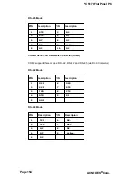
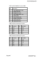
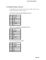
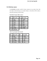
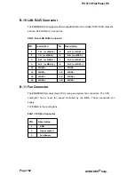
B.9 VGA Connector


The EMBEDDED provides one DB-15 female connector and one built-in 10-pin VGA 

box header connector that can be connected directly to a monochrome CRT monitor as 

well as high resolution color CRT monitor. 


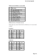
VGA1: DB-15 Female VGA Connector


PIN Description PIN Description


RED 

GREEN 


BLUE 

N/C 


GND 

GND 


GND 

GND 


VCC 

10 

GND 


11 

N/C 

12 

DDC DAT 


13 

HSYNC 

14 

VSYNC 


15 

DDC CLK 


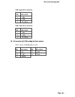
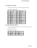
CN14: 10-pin Header VGA Connector


PIN Description PIN  Description


RED 

SMCLK 


GREEN 

SMDATA 


BLUE 

GND 


H-SYNC 

GND 


V-SYNC 

10 

GND 


Page 161


Summary of Contents for PC 5170

Page 1: ...PC 5170 17 inch touch PANEL PC USER MANUAL...

Page 2: ...Page 1...

Page 3: ...Corp All rights are reserved ACNODES Technology Corp reserves the rights to alter the products described in this manual at any time without prior notice This document contains proprietary information...

Page 4: ...arm or production line control 7 If considerable amount of dust water or fluids entered the panel PC turn off the power supply immediately unplug the power cord and contact the MPC industrial panel PC...

Page 5: ...9 If any of the following situations arises get the equipment checked by service personnel o The power cord or plug is damaged o Liquid has penetrated into the equipment o The equipment has been expo...

Page 6: ...have created products to help improve the process of cleaning Panel PCs and peripherals users can also use household items to clean their computers and peripherals Below is a list of some items that...

Page 7: ...r possible it is better to use lint free swabs such as foam swabs ESD PRECAUTIONS Observe all conventional anti ESD methods while handling the components contained within the LCD should the need arise...

Page 8: ...AUTION both capitalized and bold and is followed by text in italics The italicized text is the cautionary message NOTE These messages inform the reader of essential but non critical information These...

Page 9: ...el 23 1 2 6 Left Panel 24 1 2 7 Right Panel 24 1 2 8 Frame 25 1 3 PC 5170 INTERNAL OVERVIEW 26 1 4 PC 5170 SPECIFICATIONS 26 1 4 1 Preinstalled Hardware Components 26 1 4 2 System Specifications 26 1...

Page 10: ...S Setup JP1 47 3 5 4 COM2 Port RS232 422 485 Selection JP10 JP20 47 3 5 5 COM port RI and Voltage Selection 48 3 5 6 CPU Voltage Setting S3 50 3 5 7 Keyboard and Mouse Power Source Setting JP18 50 3 5...

Page 11: ...MENT 78 4 6 1 Remove the Old System Cooling Fans 78 4 6 2 Install the New System Cooling Fans 79 5 AMI BIOS 81 5 1 INTRODUCTION 82 5 1 1 Starting Setup 82 5 1 2 Using Setup 82 5 1 3 Getting Help 83 5...

Page 12: ...140 A 1 2 ACNODES Panel PC Product Series 140 A 2 PANEL PC PRODUCT SOLUTIONS 140 A 2 1 PPC 27 Series Panel PC Solutions 140 A 2 2 PPC 37 Series Panel PC Solutions 142 A 2 3 PPC 51 Series Panel PC Sol...

Page 13: ...Page 11...

Page 14: ...COMPACT FLASH TYPE II STORAGE CARD SOCKET 166 B 17 ATX POWER CONNECTOR 167 B 18 ATX 12V POWER CONNECTOR 167 B 19 INTERNAL SWITCHES AND INDICATORS 168 B 20 SERIAL ATA CONNECTOR 168 C BIOS CONFIGURATION...

Page 15: ...53 Figure 3 5 CD Drive Adapter Installation 54 Figure 3 6 CD Drive Retention Screws 54 Figure 3 7 Remove CD Drive 55 Figure 3 8 CD Drive Blank Plate Assembly 55 Figure 3 9 CD Drive Blank Plate Assemb...

Page 16: ...Retention Screws Bottom Panel 74 Figure 4 7 Elevated Platform Retention Screws PCI Riser Card 74 Figure 4 8 DIMM Socket Clip Locations 75 Figure 4 9 PSU Motherboard Connectors 76 Figure 4 10 PSU Bott...

Page 17: ...Settings 47 Table 3 5 COM1 RI and Voltage Selection Jumper 48 Table 3 6 COM1 RI Voltage Selection Jumper 48 Table 3 7 COM2 RI and Voltage Selection Jumper 48 Table 3 8 COM2 RI Voltage Selection Jumper...

Page 18: ...OS Menu 10 General ACPI Configuration 106 BIOS Menu 11 Advanced ACPI Configuration 107 BIOS Menu 12 MPS Configuration 110 BIOS Menu 13 USB Configuration 112 BIOS Menu 14 PCI PnP Configuration 114 BIOS...

Page 19: ...ctor FFIO Flexible File Input Output FIFO First In First Out FSB Front Side Bus IrDA Infrared Data Association HDD Hard Disk Drive IDE Integrated Data Electronics I O Input Output ICH4 I O Controller...

Page 20: ...PC 5170 Flat Panel PC THIS PAGE IS INTENTIONALLY LEFT BLANK Page 18 ACNODES Corp...

Page 21: ...PC 5170 Flat Panel PC Chapter 1 1 Introduction Page 19...

Page 22: ...5170 8520 T R Intel Pentium 4 Celeron D 478 Yes Table 1 1 PC 5170 Model Variation 1 1 2 PC 5170 Flat Panel PC Applications The PC 5170 flat panel PC is designed for rigorous industrial environments w...

Page 23: ...screen aluminum front panel and heavy duty steel rear and side panels The rear panel provides screw holes for wall and an arm mounting The right panel provides access to a slim type CD drive bay and...

Page 24: ...PC 1 2 3 Rear Panel The rear panel has a fan vent four VESA standard mounting holes and several retention screw holes The VESA mounting holes are circled in Figure 1 2 Figure 1 2 PC 5170 Rear View Pa...

Page 25: ...2 5 PC 5170 Bottom Panel The bottom panel shown in Figure 1 4 has the following interfaces 19 1 x Power input connector 20 1 x Power switch 21 6 x USB connectors 22 1 x Reset button 23 2 x RJ 45 GbE...

Page 26: ...two fan vents and four retention screws for securing the two internal fans The retention screws are circled in Figure 1 5 Figure 1 5 Left View 1 2 7 Right Panel The right side panel provides access to...

Page 27: ...Figure 1 6 Left View 1 2 8 Frame An aluminum frame surrounds the 17 TFT LCD screen The back of the aluminum frame has sixteen mounting screw holes These screws are circled in Figure 1 7 Figure 1 7 Fr...

Page 28: ...reen Below the metal sheet is a circuit board that is connected to the screen and the motherboard The three levels of components can be seen in Figure 1 8 Figure 1 8 Internal Components 1 4 PC 5170 Sp...

Page 29: ...en Optional 5 wire resistive type touch screen with RS 232 interface Display Support Dual Display Add On Card Optional Support PCI and CFII Drive Bay Power Supply One 2 5 HDD bay with anti shock One s...

Page 30: ...ications The PC 5170 comes with a EMBEDDED motherboard The technical specifications of the motherboard are listed in Table 1 3 SPECIFICATION DETAIL CPU Socket 478 base Intel Pentium 4 Celeron D Northb...

Page 31: ...1 3 Motherboard Specifications 1 4 4 Flat Panel Screen The PC 5170 comes with a 17 TFT LCD monitor at the front of the flat panel PC Figure 1 1 The specifications for the LCD monitor are shown in Tabl...

Page 32: ...with an 180W AC DC 1U RoHS compliant ATX power supply The PSU has an MTBF greater than 100 000 hours The maximum power output for the PSU is shown below 1 3 3V and 5V Combined Power 61W MAX 2 3 3V 5V...

Page 33: ...AC 80A Max for 230VAC Voltage V 3 3V 5V 12V 12V 5VSB Min Load A 0 3A 0 3A 1 5A 0A 0A OUTPUT Max Load A 16 8A 12A 10A 0 8A 2A Ripple and Noise mV 50mV 50mV 120mV 120mV 50mV 3 3V 5V 61W 3 3V 5V 12V 160W...

Page 34: ...PC 5170 Flat Panel PC 1 5 Dimensions The dimensions of the PC 5170 flat panel PC are shown in Figure 1 9 below Figure 1 9 Dimensions units in mm Page 32 ACNODES Corp...

Page 35: ...PC 5170 Flat Panel PC Chapter 2 2 EMBEDD ED Motherboard...

Page 36: ...Page 33...

Page 37: ...Southbridge Chipsets The following chipsets are preinstalled on the board 34 Northbridge Intel 852GM 35 Southbridge ICH5 The following two sections Section 2 3 2 and Section 2 3 3 list some of the fea...

Page 38: ...P LVDS interface 47 Intel Embedded Graphics Drivers o Graphics interface support o Multi monitor support o Dynamic display mode support o Embedded video BIOS 2 3 3 ICH5 Southbridge Chipset The ICH5 so...

Page 39: ...ltage Regulator INTVR for the Suspend wells 56 Enhanced DMA Controller o Two cascaded 8237 DMA controllers o PCI DMA Supports PC PCI Includes two PC PCI REQ GNT pairs o Supports LPC DMA o Supports DMA...

Page 40: ...ment arbitration between CPU system memory and graphics memory Intel Extreme Graphics 2 specifications are listed below 62 Enhanced 2D o 256 bit internal path o 8 16 32bpp o DirectDraw GDI GDI o Anti...

Page 41: ...Connectors and Slots The peripheral device connectors interfaces and slots on the EMBEDDED motherboard are listed in the sections below 2 5 1 OEM Options Many of the peripheral device connectors liste...

Page 42: ...arallel port connector 82 1 x Reset connector 83 2 x Serial ATA connectors 84 6 x Serial port connectors 85 6 x USB connectors 86 1 x VGA connector 2 5 4 External Peripheral Device Connectors The peri...

Page 43: ...PC 5170 Flat Panel PC THIS PAGE IS INTENTIONALLY LEFT BLANK Page 40 ACNODES Corp...

Page 44: ...PC 5170 Flat Panel PC Chapter 3 3 Installation and Configuration Page 41...

Page 45: ...make sure that at least two people are assisting with the procedure 4 Anti static Discharge If a user open the rear panel of the PC 5170 to configure the jumpers or plug in added peripheral devices gr...

Page 46: ...stic cover stuck to the screen Only remove the plastic cover after the PC 5170 flat panel PC has been properly installed The plastic cover ensures the screen is protected during the installation proce...

Page 47: ...x CPU cooler 1151 x CD ROM installation kit 1161 x FDD installation kit 1171 x HDD bracket 1181 x Jumper pack 1191 x Wall mounting kit 1201 x Panel mounting kit 1211 x Touch screen driver CD T R mode...

Page 48: ...3 1 Jumper Type Label Clear CMOS Setup 3 pin header JP1 COM RI and Voltage Selection 3 pin header JP6 JP7 JP8 JP9 JP13 JP14 JP15 JP16 COM2 RS 232 422 485 Setup 12 pin header JP10 6 pin header JP20 Com...

Page 49: ...Cover Retention Screws 3 5 2 CF Card Setup JP12 The CF Card Setup jumper configures a CF card as either the slave or the master JP12 DESCRIPTION Open Slave Default Close Master Table 3 2 CF Card Setup...

Page 50: ...the F1 to enter the CMOS Setup menu Then do one of the following 123Enter the correct CMOS setting 124Load Optimal Defaults After one of the above has been done save the changes and exit the CMOS Set...

Page 51: ...r JP7 DESCRIPTION 2 3 closed COM1 RI PIN Use Voltage 12V 1 2 closed COM1 RI PIN Use Voltage 5V Table 3 6 COM1 RI Voltage Selection Jumper NOTE The use of pin 2 3 or pin 1 2 of JP7 does not make any di...

Page 52: ...COM3 RI and Voltage Selection Jumper JP13 DESCRIPTION 2 3 closed COM3 RI PIN Use Voltage 12V 1 2 closed COM3 RI PIN Use Voltage 5V Table 3 10 COM3 RI Voltage Selection Jumper Use JP14 and JP16 to set...

Page 53: ...CPU is then set to 1 3V S3 DESCRIPTION All Open Pentium 4 CPU Default 1 2 7 8 11 12 closed Pentium 4 M CPU 1 3V Table 3 13 CPU Voltage Setting 3 5 7 Keyboard and Mouse Power Source Setting JP18 JP18 D...

Page 54: ...rm by four retention screws Remove the four retention screws from the elevated platform Figure 3 2 Figure 3 2 HDD Retention Screws Step 3 Step 4 Attach the HDD bracket to the HDD To do this align the...

Page 55: ...The FDD bracket is attached to the elevated platform by two retention screws Figure 3 3 Remove the two retention screws from the elevated platform Remove the FDD bracket by sliding toward the HDD Figu...

Page 56: ...ly removed two retention screws Connect the FDD ribbon cable and the power cable from the connectors on the motherboard and the PSU to the rear of the FDD Step 0 3 6 3 CD Drive Installation To install...

Page 57: ...he CD drive blank plate assembly is attached to the rear panel by two retention screws Figure 3 6 Figure 3 6 CD Drive Retention Screws Remove the two retention screws from the bottom panel and slide t...

Page 58: ...s that attach the brackets to the blank plate Figure 3 8 shows the underside of the CD drive blank plate assembly with the four screws to be removed Figure 3 8 CD Drive Blank Plate Assembly Step 7 Att...

Page 59: ...ages shown in the Figure 3 9 Step 8 Step 9 Slide the CD drive into the PC 5170 and align the two retention screw holes in the side of the CD drive bracket with the retention screw holes on the bottom...

Page 60: ...PC 5170 Flat Panel PC Figure 3 10 CD Drive Installed Page 57...

Page 61: ...are fully described below 3 7 1 Wall Mounting To mount the PC 5170 flat panel PC onto a wall please follow the steps below Step 1 Step 2 Step 3 Step 4 Step 5 Select the location on the wall for the wa...

Page 62: ...against the rear panel see Figure 3 12 Align the mounting screws on the monitor rear panel with the mounting holes on the bracket Carefully insert the screws through the holes and gently pull the moni...

Page 63: ...on the top panel of the panel PC Carefully mark the location of the wall mounting kit screw holes on the wall Drill a pilot hole at the marked location on the wall Secure the wall mounting kit to the...

Page 64: ...no more than 6mm Step 1 Step 2 Select the position on the panel to mount the PC 5170 Cut out a section of the panel that corresponds to the rear panel dimensions of the PC 5170 Take care that the pane...

Page 65: ...e formed holes along the edges of the PC 5170 behind the metal frame Refer to the mounting kit packing list for the required number of mounting clamps Figure 3 15 Panel Mounting Clamp Positions Step 5...

Page 66: ...the surface it uses as a base To do this refer to the installation documentation that came with the mounting arm NOTE When purchasing the arm please ensure that it is VESA compliant and that the arm...

Page 67: ...anel PC can be installed into a cabinet or rack To do this please follow the steps below Step 1 The back of the metal frame surrounding the PC 5170 flat panel PC has several retention screw holes for...

Page 68: ...e retention screw holes in the cabinet rack bracket Secure the cabinet rack bracket to the monitor by inserting and tightening the retention screws Figure 3 18 Figure 3 18 Secure the Rack Cabinet Brac...

Page 69: ...nnectors 3 8 1 LCD Panel Connection A conventional CRT VGA 15 pin female D SUB connector is located on the bottom panel to connect the PC 5170 flat panel PC to a second monitor NOTE To use the dual sc...

Page 70: ...tors on the external peripheral interface panel facilitate the connection of a mouse and a keyboard To connect either device plug the PS 2 connector at the end of the keyboard or mouse cable into the...

Page 71: ...PC 5170 Flat Panel PC THIS PAGE IS INTENTIONALLY LEFT BLANK Page 68 ACNODES Corp...

Page 72: ...PC 5170 Flat Panel PC Chapter 4 4 System Maintenance Page 69...

Page 73: ...ed components are described below 4 2 Motherboard Replacement A user cannot replace a motherboard If the motherboard fails it must be shipped back to ACNODES to be replaced If the system motherboard h...

Page 74: ...observed 4 3 1 Back Cover Removal Please read the warnings at the beginning of Section 4 3 before attempting to remove the PC 5170 back cover To access the panel PC internal components the back cover...

Page 75: ...re attempting to access any PC 5170 internal components The elevated platform supports the FDD CD drive and HDD Back cover removal is discussed in Section 4 3 1 To detach the elevated platform please...

Page 76: ...atform Figure 4 3 three on the top panel Figure 4 4 three on the right panel Figure 4 5 two on the bottom panel Figure 4 6 and two on the PCI riser card Figure 4 7 Remove the retention screws and lift...

Page 77: ...anel Figure 4 7 Elevated Platform Retention Screws PCI Riser Card 4 4 DIMM Replacement Please read the warnings at the beginning of Section 4 3 before attempting to access any PC 5170 internal compone...

Page 78: ...into position and the two handles have automatically locked the memory module into place Step 0 4 5 PSU Module Replacement Please read the warnings at the beginning of Section 4 3 before attempting to...

Page 79: ...om panel Figure 4 10 two connect to the internal PSU bracket Figure 4 12 which is connected to the chassis by two screws Figure 4 11 Step 4 Remove the PSU retention screws from the bottom panel Figure...

Page 80: ...tion screws that connect the PSU to the PSU bracket Figure 4 12 Step 0 Figure 4 12 PSU Bracket Retention Screws 4 5 2 Install the New PSU To install a new PSU module please follow the steps below Step...

Page 81: ...to the motherboard and disk drives Reattach the elevated platform Replace the back cover Step 0 4 6 System Cooling Fan Replacement Please read the warnings at the beginning of Section 4 3 before attem...

Page 82: ...he system cooling fans from the chassis Step 0 4 6 2 Install the New System Cooling Fans To install the new system cooling fans please follow the steps below Step 1 Step 2 Step 3 Insert the system coo...

Page 83: ...PC 5170 Flat Panel PC Step 4 Step 5 Reattach the elevated platform Replace the back cover Step 0 Page 80 ACNODES Corp...

Page 84: ...PC 5170 Flat Panel PC Chapter 5 5 AMI BIOS Page 81...

Page 85: ...sage disappears before the DELETE key is pressed restart the computer and try again 5 1 2 Using Setup Use the arrow keys to highlight items press ENTER to select use the and keys to change entries pre...

Page 86: ...to the system configuration use the jumper described in Section 0 to reset the CMOS defaults 5 1 5 BIOS Menu Bar The menu bar on top of the BIOS screen has the following main items 133Main Changes the...

Page 87: ...components The fields in System Overview cannot be changed The items shown in the system overview include 141AMI BIOS Displays auto detected BIOS information o Version Current BIOS version o Build Da...

Page 88: ...e Advanced menu BIOS Menu 2 to configure the CPU and peripheral devices through the following sub menus WARNING Setting the wrong values in the sections below may cause the system to malfunction Make...

Page 89: ...PC 5170 Flat Panel PC BIOS Menu 2 Advanced Page 86 ACNODES Corp...

Page 90: ...Configuration The CPU Configuration menu BIOS Menu 3 lists the following CPU details 153Manufacturer Lists the name of the CPU manufacturer 154Brand String Lists the brand name of the CPU being used 1...

Page 91: ...must be set to enabled Disabled DEFAULT Disables legacy OSes that cannot support CPUs with extended CUPID functions from booting up Enabled Enables legacy OSes that cannot support CPUs with extended C...

Page 92: ...iguration IDE Configuration P ATA Only Use IDE Configuration option to setup the configuration of the hard drive interfaces Disabled The hard drive interfaces are disabled P ATA Only DEFAULT The hard...

Page 93: ...e active IDE channel Both DEFAULT The primary and secondary P ATA channel are both set to be the active IDE channels S ATA Ports Definition PO 3rd P1 4th Use S ATA Ports Definition option to select th...

Page 94: ...econds 16415 seconds 16520 seconds 16625 seconds 16730 seconds 16835 seconds DEFAULT The best setting to use if the onboard IDE controllers are set to a specific IDE disk drive in the AMIBIOS is 0 sec...

Page 95: ...ces BIOS displays the status of the auto detected IDE devices The following IDE devices are detected and are shown in the IDE Configuration menu 169Primary IDE Master 170Primary IDE Slave 171Secondary...

Page 96: ...ected from the firmware of the selected IDE disk drive The drive parameters are listed as follows 175Device Lists the device type e g hard disk CD ROM etc 176Type Indicates the type of devices a user...

Page 97: ...DEFAULT The BIOS auto detects the IDE disk drive type attached to the specified channel This setting should be used if an IDE hard disk drive is attached to the specified channel CD DVD The CD DVD op...

Page 98: ...or Transfer support on the drive on the specified channel If supported the data transfer to and from the device occurs multiple sectors at a time PIO Mode Auto Use the PIO Mode option to select the ID...

Page 99: ...on the drive on the specified channel S M A R T predicts impending drive failures The S M A R T BIOS option enables or disables this function Auto DEFAULT BIOS auto detects HDD SMART support Disabled...

Page 100: ...urations for floppy disk drives BIOS Menu 6 Floppy Configuration Floppy A 1 44 MB 3 The Floppy A configuration option determines the types of the floppy drive installed in the system The following con...

Page 101: ...serial ports BIOS Menu 7 Super IO Configuration On Board Floppy Controller Enabled Disabled Allows BIOS to disable the floppy controller Enabled DEFAULT Allows BIOS to enable the floppy controller Ser...

Page 102: ...is assigned to Serial Port 2 2F8 IRQ3 DEFAULT Serial Port 2 I O port address is 3F8 and the interrupt address is IRQ3 3E8 IRQ4 Serial Port 2 I O port address is 3E8 and the interrupt address is IRQ4 2...

Page 103: ...anced parallel port mode EPP The EPP mode supports bi directional communication between the system and the parallel port device and the transmission rates between the two are much faster than the Norm...

Page 104: ...O address is 260h 280h DEFAULT Digital I O address is 280h Serial Port3 Address 3E8 Use the Serial Port3 Address option to select the base addresses for serial port 3 Disabled No base address is assig...

Page 105: ...port address is 2F0 2E0 Serial port 4 I O port address is 2E0 Serial Port4 IRQ 10 Use the Serial Port4 IRQ option to select the interrupt address for serial port 4 3 Serial port 4 IRQ address is 3 9 S...

Page 106: ...dress 2E0 Use the Serial Port6 IRQ option to select the interrupt address for serial port 6 Disabled No base address is assigned to serial port 6 3E8 Serial port 6 I O port address is 3E8 2E8 Serial p...

Page 107: ...led Disabled Disables the health monitoring function Enabled DEFAULT Enables the health monitoring function If the H W Health Function is enabled different system parameters and values are shown The s...

Page 108: ...stem voltages are monitored o Vcore o 1 50V o 3 30V o 5 00V o 12 0V o 5VSB 5 3 6 ACPI Configuration The ACPI Configuration menu BIOS Menu 9 configures the Advanced Configuration and Power Interface AC...

Page 109: ...ystem is suspended BIOS Menu 10 General ACPI Configuration Suspend Mode S1 POS Use the Suspend Mode option to specify the sleep state the system enters when it is not being used S1 POS The system ente...

Page 110: ...No Use the ACPI 2 0 Features option to enable the ACPI Advanced Configuration and Power Interface features By enabling this feature the system RSDP Root System Description Pointer is able to obtain p...

Page 111: ...provided in the RSDT APIC ACPI SCI IRQ Disabled Use APIC ACPI SCI IRQ option to enable the system to send a flag report to the ACPI OS if a SCI IRQ interrupt event is made via the APIC Disabled DEFAU...

Page 112: ...ss Mode Disabled Use the Headless Mode option to update the ACPI FACP Fixed ACPI Description Table to indicate headless operations i e a computer without a monitor keyboard and mouse Disabled DEFAULT...

Page 113: ...on MPS for OS option to specify the MPS version to be used 1 1 MPS version 1 1 is used 1 4 DEFAULT MPS version 1 4 is used 5 3 8 Remote Access Configuration Use the Remote Access Configuration menu to...

Page 114: ...te functionalities of the system Disabled DEFAULT Remote access is disabled Enabled Remote access configuration options shown below appear Serial Port Number Serial Port Mode Flow Control Redirection...

Page 115: ...13 USB Configuration USB Configuration The USB Configuration field shows the system USB configuration The items listed are 191Module Version x xxxxx xxxxx USB Devices Enabled The USB Devices Enabled f...

Page 116: ...SB mouse or USB keyboard does not become available until a USB compatible operating system is fully booted with all USB drivers loaded When this option is enabled any attached USB mouse or USB keyboar...

Page 117: ...ING Setting wrong values for the BIOS selections in the PCIPnP BIOS menu may cause the system to malfunction BIOS Menu 14 PCI PnP Configuration Plug Play O S No Use the Plug Play O S BIOS option to sp...

Page 118: ...Timer 64 Use the PCI Latency Timer option to specify the PCI latency time The latency time is measured in units of PCI clock cycles for the PCI device latency timer register Configuration options are...

Page 119: ...ys check with the adapter card manual first before modifying the default settings in the BIOS PCI IDE BusMaster Disabled Use the PCI IDE BusMaster BIOS option to enable or prevent PCI IDE busmastering...

Page 120: ...card is installed in PCI Slot 4 PCI Slot 5 PCI Slot 5 is selected as the location of the OffBoard PCI IDE adapter card Only select this slot if the adapter card is installed in PCI Slot 5 PCI Slot 6 P...

Page 121: ...cific DMA channel to a particular PCI PnP device Available DEFAULT The specified DMA is available to be used by PCI PnP devices Reserved The specified DMA is reserved for use by Legacy ISA devices Ava...

Page 122: ...S option to specify the amount of memory that should be reserved for legacy ISA devices Disabled DEFAULT No memory block reserved for legacy ISA devices 16K 16KB reserved for legacy ISA devices 32K 32...

Page 123: ...PC 5170 Flat Panel PC 5 5 Boot Use the Boot menu BIOS Menu 15 to configure system boot options BIOS Menu 15 Boot Page 120 ACNODES Corp...

Page 124: ...16 Boot Settings Configuration Quick Boot Enabled Use the Quick Boot BIOS option to make the computer speed up the boot process Disabled No POST procedures are skipped Enabled DEFAULT Some POST proce...

Page 125: ...k setting must be modified during boot up Off Does not enable the keyboard Number Lock automatically To use the 10 keys on the keyboard press the Number Lock key located on the upper left hand corner...

Page 126: ...to use a PS 2 mouse Auto DEFAULT The system auto adjusts PS 2 mouse support 5 5 2 Boot Device Priority Use the Boot Device Priority menu BIOS Menu 17 to specify the boot sequence from the available d...

Page 127: ...ve 1st FLOPPY DRIVE NOTE Only the drives connected to the system are shown For example if only one FDD is connected only 1st Drive is listed The boot sequence from the available devices is selected If...

Page 128: ...led If a supervisor password must be installed select this field and enter the password After the password has been added Install appears next to Change Supervisor Password Change User Password Use th...

Page 129: ...menu BIOS Menu 20 to access the NorthBridge and SouthBridge configuration menus WARNING Setting the wrong values for the Chipset BIOS selections in the Chipset BIOS menu may cause the system to malfu...

Page 130: ...thBridge Chipset Configuration DRAM Frequency Auto Use the DRAM Frequency option to specify the DRAM frequency or allow the system to automatically detect the DRAM frequency 200MHz Sets the DRAM frequ...

Page 131: ...bled DEFAULT DRAM timing parameter are set according to the DRAM Serial Presence Detect SPD If the Configure DRAM Timing by SPD option is disabled the following configuration options appear 219DRAM CA...

Page 132: ...isable Enable 1MB 1MB of memory used by internal graphics device Enable 4MB 4MB of memory used by internal graphics device Enable 8MB DEFAULT 8MB of memory used by internal graphics device Enable 16MB...

Page 133: ...below 225CRT 226LFP 227CRT LFP DEFAULT Flat Panel Type 640x480 Use the Flat Panel Type option to select the type of flat panel connected to the system Configuration options are listed below 228640x480...

Page 134: ...22 the southbridge chipset to be configured BIOS Menu 22 SouthBridge Chipset Configuration OnBoard AC97 Audio Auto Use the OnBoard AC97 Audio option to enable or disable the AC 97 CODEC Auto DEFAULT T...

Page 135: ...Power Management APM Enabled Use the Power Management APM BIOS option to enable access to the advanced power management features If this option is disabled the only other option on the screen is the...

Page 136: ...fies in what system mode the hard disk device can be turned off Disabled The hard disk cannot be turned off in the Suspend or Standby mode Standby The hard disk can be turned off in the Standby mode S...

Page 137: ...ed state The options are listed below 249Disabled Default 2501 Min 2512 Min 2524 Min 2538 Min 25410 Min 25520 Min 25630 Min 25740 Min 25850 Min 25960 Min Power Button Mode On Off Use the Power Button...

Page 138: ...state when there is activity on the RI ring in modem line That is the system will be roused by an incoming call on a modem Disabled DEFAULT Wake event not generated by an incoming call Enabled Wake e...

Page 139: ...rs with values that can be selected RTC Alarm Date Days System Time After setting the alarm the computer turns itself on from a suspend state when the alarm goes off 5 9 Exit Use the Exit menu BIOS Me...

Page 140: ...nges and Exit option to exit the BIOS configuration setup program without saving the changes made to the system Discard Changes Use the Discard Changes option to discard the changes and remain in the...

Page 141: ...PC 5170 Flat Panel PC THIS PAGE IS INTENTIONALLY LEFT BLANK Page 138 ACNODES Corp...

Page 142: ...PC 5170 Flat Panel PC Appendix A A ACNODES Panel PC Product Line...

Page 143: ...Page 139...

Page 144: ...appendix introduces the full range of ACNODES panel PC products A 1 2 ACNODES Panel PC Product Series There are currently four panel PC product series The four series are listed below 260PPC 27 Serie...

Page 145: ...B 2 0 2 x USB 2 0 1 x PS 2 1 x PS 2 1 x VGA out 1 x VGA out 2 x LAN 2 x LAN 1 x Audio 3 x Audio 1 x IDE 1 x IDE 2 x SATA 2 x SATA SSD CF Type II CF Type II HDD Drive Bay 1 x 2 5 SATA IDE HDD 1 x 2 5 S...

Page 146: ...ium M Celeron M ULV Celeron M 1GHz 800MHz Pentium M Celeron M ULV Celeron M 1GHz 800MHz Pentium M Celeron M ULV Celeron M 1GHz 800MHz Pentium M Celeron M ULV Celeron M 1GHz Pentium M Celeron M ULV Cel...

Page 147: ...er 80W 55W AC Adapter 80W 55W AC Adapter 150W ATX Power 150W ATX Power Mounting Stand Rack Wall Panel Arm Stand Rack Wall Panel Arm Stand Rack Wall Panel Arm Stand Rack Wall Panel Arm Stand Rack Wall...

Page 148: ...D RAM 2 x DDR 266 333MHz DIMM socket up to 2GB 2 x DDR 266 333MHz DIMM socket up to 2GB 2 x DDR 266 333MHz DIMM socket up to 2GB I O Ports 1 x RS 232 422 485 1 x RS 232 422 485 1 x RS 232 422 485 4 x...

Page 149: ...mpliant Protection Touch Screen Resistive Type 5 wire with RS 232 Interface Resistive Type 5 wire with RS 232 Interface Resistive Type 5 wire with RS 232 Interface Table A 3 PPC 51 Series Panel PC Sol...

Page 150: ...t 1 x PCI 1 x PCIe 1 x PCI 1 x PCIe 1 x PCI 1 x PCIe HDD Drive Bay 2 x 3 5 SATA IDE HDD w Anti Shock 2 x 3 5 SATA IDE HDD w Anti Shock 2 x 3 5 SATA IDE HDD w Anti Shock FDD Drive Bay 1 x Slim FDD 1 x...

Page 151: ...786 Brightness 350 cd m2 LCD Color 262K Viewing Angle 120 100 Backlight MTBF 50000hrs SBC Model A 300 Socket 479 CPU Pentium M Celeron M ULV Celeron M 1GHz 800MHz RAM 2 x DDR 266 333MHz DIMM socket up...

Page 152: ...rive Bay Power Supply 150W ATX Power Mounting Stand Rack Wall Panel Arm Dimension WxDxH mm 410 x 309 x 110 Weight 8 12kg Front Panel Protection IP 65 compliant Touch Screen Resistive Type 5 wire with...

Page 153: ...PC 5170 Flat Panel PC Appendix B B Interface Connectors Page 149...

Page 154: ...pin daisy chain driver connector cable PIN Description PIN Description 1 GROUND 2 REDUCE WRITE 3 GROUND 4 N C 5 GROUND 6 N C 7 GROUND 8 INDEX 9 GROUND 10 MOTOR ENABLE A 11 GROUND 12 DRIVE SELECT B 13...

Page 155: ...N Description PIN Description 1 RESET 2 GND 3 DATA 7 4 DATA 8 5 DATA 6 6 DATA 9 7 DATA 5 8 DATA 10 9 DATA 4 10 DATA 11 11 DATA 3 12 DATA 12 13 DATA 2 14 DATA 13 15 DATA 1 16 DATA 14 17 DATA 0 18 DATA...

Page 156: ...TA 4 7 DATA 5 8 DATA 6 9 DATA 7 10 ACKNOWLEDGE 11 BUSY 12 PAPER EMPTY 13 PRINTER SELECT 14 AUTO FORM FEED 15 ERROR 16 INITIALIZE 17 PRINTER SELECT LN 18 GND 19 GND 20 GND 21 GND 22 GND 23 GND 24 GND 2...

Page 157: ...7 REQUEST TO SEND RTS 8 CLEAR TO SEND CTS 9 RING INDICATOR RI COM2 Serial Port 2 x 5 Pin Header Connector COM2 Support three modes RS 232 RS 422 and RS 485 via 2 x 5 pin box header connector RS 232 M...

Page 158: ...20B Serial Port DB 9 Male Connector COM2 COM2 supports three modes RS 232 RS 422 and RS 485 via DB 9 Connector RS 232 Mode PIN Description PIN Description 1 DCD 6 DSR 2 RXD 7 RTS 3 TXD 8 CTX 4 DTR 9 R...

Page 159: ...C 4 NC 9 Voltage 5 NC COM3 Serial Port 2x5 Pin Header Connector PIN Description PIN Description 1 DCD 2 DSR 3 RXD 4 RTS 5 TXD 6 CTX 7 DTR 8 RI 9 GND 10 NC COM4 Serial Port 2x5 Pin Header Connector PIN...

Page 160: ...ND GND 6 DATA SET READY DSR 7 REQUEST TO SEND RTS 8 CLEAR TO SEND CTS 9 RING INDICATOR RI COM5 Serial Port 2x5 Pin Header Connector PIN Description PIN Description 1 DCD 2 DSR 3 RXD 4 RTS 5 TXD 6 CTX...

Page 161: ...ard and mouse connectors CN23A Purple Extended Keyboard 6 pin Mini Din Connector PIN Description 1 KB DATA 2 NC 3 GND 4 VCC 5 KB CLOCK 6 NC CN23B Green Extended Mouse 6 pin Mini Din Connector PIN Desc...

Page 162: ...D 5 5V B 6 External Switches and Indicators CN8 Multi Panel PIN Description PIN Description 1 SPEAKER 11 POWER VCC 2 N C 12 N C 3 N C 13 GND 4 5V 14 KEYLOCK 5 RESET SW 15 GND 6 GND 16 GND 7 IDE LED 17...

Page 163: ...DDED has eight built in USB ports for the future I O bus expansion CN26 CN27 CN28 8 PIN Header USB Connectors PIN Description 1 8 VCC 3 6 USBD0 5 4 USBD0 7 2 GND CN25 2 External USB Connectors PIN Des...

Page 164: ...ports Serial Infrared SIR or Amplitude Shift Keyed IR ASKIR interfaces To use the IrDA port configure the FIR or ASKIR model in the Peripheral Setup COM2 in BIOS Then the normal RS 232 COM2 will be di...

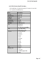
Page 165: ...e CRT monitor as well as high resolution color CRT monitor VGA1 DB 15 Female VGA Connector PIN Description PIN Description 1 RED 2 GREEN 3 BLUE 4 N C 5 GND 6 GND 7 GND 8 GND 9 VCC 10 GND 11 N C 12 DDC...

Page 166: ...TX or MDX0 6 RX or MDX1 3 RX or MDX1 7 N C or MDX3 4 N C or MDX2 8 N C or MDX3 13 MDX0 17 MDX2 14 MDX0 18 MDX1 15 MDX1 19 MDX3 16 MDX2 20 MDX3 B 11 Fan Connector The EMBEDDED provides three CPU cooli...

Page 167: ...Description 1 GND 2 12V 3 Fan Sensor FAN3 System Fan Connector PIN Description 1 GND 2 12V 3 Fan Sensor B 12 Inverter LCD Backlight Connector CN12 Inverter LCD Backlight Connector PIN Description PIN...

Page 168: ...PIN Description 1 GND 2 GND 3 A0P 4 A0M 5 A1P 6 A1M 7 A2P 8 A2M 9 CLK1P 10 CLK1M 11 A3P 12 A3M 13 GND 14 GND 15 A4P 16 A4M 17 A5P 18 A5M 19 A6P 20 A6M 21 CLK2P 22 CLK2M 23 A7P 24 A7M 25 GND 26 GND 27...

Page 169: ..._L 2 GND 3 GND 4 LINE OUT_R CN24 Audio Jack Color Description RED MIC IN BLUE LINE IN GREEN SPEAK OUT B 15 Digital Input Output CN6 Digital Input Output PIN Description PIN Description 1 GND 2 5V 3 Ou...

Page 170: ...26 CARD DETECT1 2 D3 27 D11 3 D4 28 D12 4 D5 29 D13 5 D6 30 D14 6 D7 31 D15 7 CS1 32 CS3 8 N C 33 N C 9 GROUND 34 IOR 10 N C 35 IOW 11 N C 36 OBLIGATORY TO PULL HIGH 12 N C 37 IRQ15 13 VCC 38 VCC 14...

Page 171: ...ription 11 3 3V 1 3 3V 12 12V 2 3 3V 13 GND 3 GND 14 PS ON 4 5V 15 GND 5 GND 16 GND 6 5V 17 GND 7 GND 18 5V 8 Power good 19 5V 9 5VSB 20 5V 10 12V B 18 ATX 12V Power Connector This connector supports...

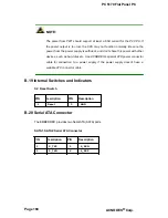
Page 172: ...es such as hard disk etc Use ACNODES s special ATX power connector cable for connection to a power supply if the power supply doesn t have a suitable ATX connector cable B 19 Internal Switches and Ind...

Page 173: ...PC 5170 Flat Panel PC Appendix C C BIOS Configuration Options Page 169...

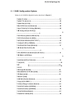
Page 174: ...Definition PO 3rd P1 4th 90 Configure S ATA as RAID No 90 Hard Disk Write Protect Disabled 91 IDE Detect Time Out Sec 35 1 9 ATA PI 80Pin Cable Detection Host Device 91 IDE Master and IDE Slave 2 9 Au...

Page 175: ...Page 170 ACNODES Corp...

Page 176: ...ion Enabled 104 Suspend Mode S1 POS 106 ACPI 2 0 Features No 107 ACPI APIC Support Enabled 108 APIC ACPI SCI IRQ Disabled 108 AMI OEMB table Enabled 108 Headless Mode Disabled 109 MPS Revision 1 4 110...

Page 177: ...25 Change User Password 125 DRAM Frequency Auto 127 Configure DRAM Timing by SPD Enabled 128 Memory Hole Disabled 128 Init Graphic Adapter Priority PCI Int VGA 129 Internal Graphics Mode Select Enable...

Page 178: ...el PC Resume on PME Disabled 135 Resume On RTC Alarm Disabled 135 RTC Alarm Date Days 136 System Time 136 Save Changes and Exit 137 Discard Changes and Exit 137 Discard Changes 137 Load Optimal Defaul...

Page 179: ...PC 5170 Flat Panel PC THIS PAGE IS INTENTIONALLY LEFT BLANK Page 174 ACNODES Corp...

Page 180: ...PC 5170 Flat Panel PC Appendix D D Software Drivers Page 175...

Page 181: ...perating systems 265Microsoft Windows versions o Microsoft Windows 95 o Microsoft Windows 98 o Microsoft Windows ME o Microsoft Windows 2000 o Microsoft Windows NT o Microsoft Windows XP o Microsoft W...

Page 182: ...ion is for driver installation using a Windows 2000 OS If a different OS is installed please refer to the driver user manual for the relevant OS The driver user manuals can be accessed by selecting Us...

Page 183: ...izard is ready a welcome screen appears Figure D 3 Figure D 3 Welcome Screen Step 6 Step 7 To continue the installation process click NEXT An Install PS 2 interface driver screen appears Figure D 4 It...

Page 184: ...Driver Step 8 Four point calibration options are then selected Four point calibrations can be done every time a user boots up during the next time the system boots or never Select when a four point ca...

Page 185: ...oller is plugged into the system click OK Figure D 6 Touch Monitor USB Touch Controller Confirmation Step 10 The user is then prompted to select a file directory in which the touch kit controller is i...

Page 186: ...ep 11 The user is then prompted to select a file directory in which the program icons are saved Figure D 8 The default folder is TouchKit If a different folder must be used select a folder from the li...

Page 187: ...PC 5170 Flat Panel PC Figure D 8 Program Icon Directory Step 12 The program then starts installing Figure D 9 Figure D 9 Installing Page 182 ACNODES Corp...

Page 188: ...he computer later Figure D 10 Select when the computer should be restarted and click FINISH to complete the driver installation procedure Figure D 10 Installation Complete D 3 Touch Panel Driver Confi...

Page 189: ...PC 5170 Flat Panel PC THIS PAGE IS INTENTIONALLY LEFT BLANK Page 184 ACNODES Corp...

Page 190: ...PC 5170 Flat Panel PC E Index Page 185...

Page 191: ...etaching the Elevated Platform 72 Digital Input Output 165 Dimensions 32 DIMM Replacement 74 E Embedded system solutions 140 Ethernet Connection 67 External Peripheral Device Connectors 39 External Sw...

Page 192: ...arallel Port 152 Parallel Port Connection 67 PCI E IDE Disk Drive Connector 151 Power Supply 30 Preinstalled Components 42 Preinstalled Hardware Components 26 PSU Module Replacement 75 S Safety Precau...

Reviews: