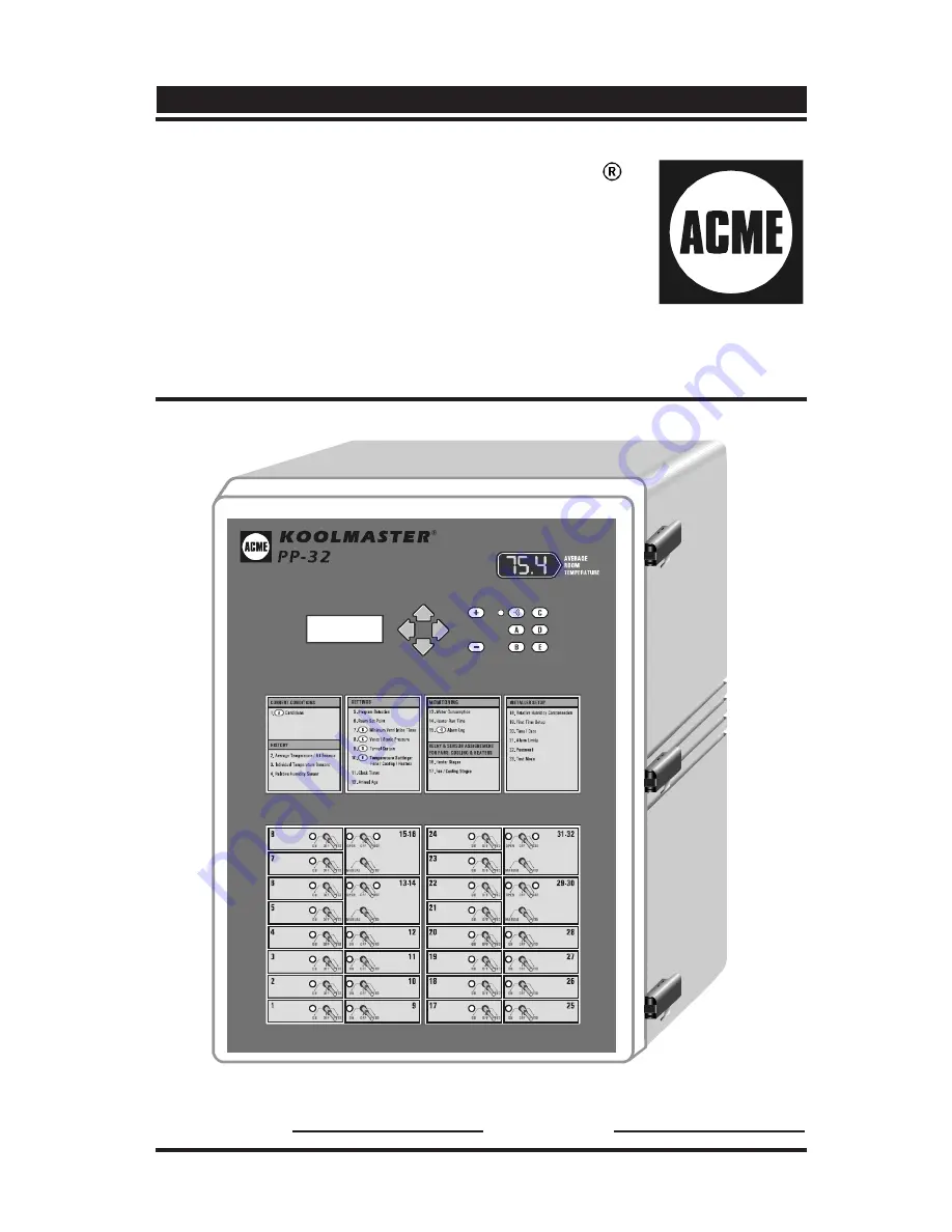
KOOLMASTER
PP-32
CONTROLLER
Read this guide carefully before using the controller.
ENVIRONMENTAL
MANAGEMENT
SYSTEM
SERIAL NUMBER: DATE:
R01
Page 1: ...KOOLMASTER PP 32 CONTROLLER Read this guide carefully before using the controller ENVIRONMENTAL MANAGEMENT SYSTEM SERIAL NUMBER DATE R01...
Page 2: ...NOTICE Every effort has been made to ensure that this manual is complete accurate and up to date The information contained in it is however subject to change without notice due to further developments...
Page 3: ...ing DWR F 1A s ID numbers 21 5 5 1 2 Adjusting the Air Inlet Compensation 22 5 5 2 Vent Door Settings 23 5 5 2 1 Adjusting Static Pressure Set Points 26 5 5 2 2 Adjusting Vent Doors Open Close Off Tim...
Page 4: ...mperature Influence 55 5 13 2 4 Adjusting Static Pressure Alarms 56 5 13 3 Resetting the Alam Log 58 5 14 INSTALLATION 59 5 14 1 Step by Step Installation Guide 59 5 14 2 Password Settings 61 5 14 3 I...
Page 5: ...tion 83 5 15 3 3 Adjusting Mist or Kool Cel Shutoff 84 5 15 3 4 Adjusting Heater Timer Cycle 84 5 15 4 Calibrating Sensors 86 5 15 4 1 Calibrating Room and Outside T Sensors 86 5 15 4 2 Calibrating th...
Page 6: ...n overload or overvoltage we recommend installing an additional protection device on the controller s supply circuit The room temperature where the controller is located MUST ALWAYS REMAIN BETWEEN 32...
Page 7: ...ither continuously or intermittently to reduce the level of humidity and supply oxygen to the room TEMPERATURE AND MINIMUM VENTILATION CURVES The controller can automatically change the temperature se...
Page 8: ...CONTROL OF AIR INLET MOVEMENT If the PP 32 is used in combination with one or more DWR F 1A controllers the movement of air inlets can be coordinated with the operation of the fans using a potentiome...
Page 9: ...9 KOOLMASTER PP 32 REV 01 3 LOCATION OF THE CONTROLS NAVIGATION BUTTONS ADJUSTMENT BUTTONS LCD DISPLAY SHORTCUT KEYS MAIN MENUS 32 ON OFF RELAYS ALARM STATUS LED Front Panel LED DISPLAY...
Page 10: ...t a menu option The left arrow key is used to return to the previous menu display Adjustment Buttons These two push buttons allow the user to adjust the value of a parameter that is shown on the displ...
Page 11: ...water from entering the control ler The enclosure must be mounted in a location that will allow the cover to be completely opened right up against the wall Push on the locking devices to open the encl...
Page 12: ...nsshouldnot be under 18 AWG to ensure the cable entry is liquid tight Do not ground the shielding It is preferable to solder the cable joint to ensure a proper contact between the two cables CAUTION D...
Page 13: ...inlet controllers are connected to the PP 32 use id numbers within the range 4 15 Id numbers 1 2 and 3 are reserved for another purpose Refer to section 5 5 1 1 to set the proper ID numbers terminal a...
Page 14: ...D H R N O I T A L I T N E V M U M I N I M E L B A N E N O I T A S N E P M O C 8 D E S U T O N 9 D E S U T O N 0 1 D E S U T O N 1 1 D E S U T O N 2 1 D E S U T O N WARNING 4 2 SETTING THE DIP SWITCHE...
Page 15: ...the barn Static Pressure current static pressure in the barn Fan Stage shows which fan stage is currently active Program shows the selected program Fan On Time sec fans on time in minimum ventilation...
Page 16: ...n buttons to select 5 Program Select from the main menu then press the right arrow key The program that is currently in use is flashes on the display Use the adjustment buttons to select the proper pr...
Page 17: ...tion a Temp Settings Summr Use the adjustment buttons to select the proper season winter summer The start and stop temperatures of heating and ventilation stages that are associ ated with this seasons...
Page 18: ...using the navigation buttons then press the right arrow key The current set point is displayed as well as the on off state of the temperature curve If the temperature curve is OFF the set point flash...
Page 19: ...d over time by using a curve Refer to section 5 15 2 for further information on the minimum ventilation curve NotethattheminimumventilationcurvemustbeTURNEDOFF in order to adjust minimum ventilation s...
Page 20: ...ollow the procedure above to adjust the set point 5 4 2 Adjusting Minimum Ventilation s Cycle Time Fans Cycle Time in minimum ventilation can be adjusted from 0 to 900 seconds 15 minutes in increments...
Page 21: ...meter Feedback from Inlets If air inlets operate according to potentiometer feedback modules DWR F 1A the PP 32 controller adjusts the air inlets opening according to ventilation stages As the tempera...
Page 22: ...igned by the user For example if the compensation value is set to 5 F and the inlet s sensors read 3 F above the average controller temperature the inlet will open of 15 to help decrease the temperatu...
Page 23: ...before fans start running The same delay is used to close the vent doors when the stage 1 fans return to a stop Static Pressure Alarm alarms can be set off if the static pressure remains below or exce...
Page 24: ...e when the start temperature of stage 5 is reached the vent doors start operating according to the second group of static pressure set points The first group of set points is being used once again whe...
Page 25: ...ure decreases 5 F further than the user defined value the second group of set points is used Refer to the installation setup section to activate the second group of static pressure set points see sec...
Page 26: ...the LO static pressure set point is selected Close At Use the adjustment buttons to adjust the low static pressure set point Close At to the desired value then press the down arrow key The hi static p...
Page 27: ...then press the right arrow key Note that this menu is only available if the static pressure sensor has been enabled during the installation setup see sec 5 14 3 Press the right arrow key to select the...
Page 28: ...e fan stage above which the vent doors will be closed 5 5 2 4 2nd Group of Pressure Set Points at Stage X The following procedure shows how to select the fan stage above which the second group of stat...
Page 29: ...re Set Points at Outside T X The following procedure shows how to select the outside temperature below which the second group of static pressure set points starts being used It also explains how to ad...
Page 30: ...ce the LO static pressure set point 2 Close At is selected Use the adjustment buttons to adjust the 2nd low static pressure set point Close At to the desired value then press the down arrow key The HI...
Page 31: ...s also set to limit the curtain s opening When the start temperature of the first tunnel stage is reached the tunnel curtain opens during half of the opening time that is associated with this stage Wh...
Page 32: ...age has been reached When the curtain starts opening it first opens during the pre opening delay Fans of the first tunnel stage are then activated The following diagram sums up the operation of the tu...
Page 33: ...ent doors close until the static pressure level reaches Hi Static Pressure Limit 0 01 WC 6 Steps 4 and 5 are repeated until the vent doors run for over 30 seconds without reaching Hi Static Pressure L...
Page 34: ...ttons to set the minimum animal age to the desired value Press the left arrow key to exit this menu 5 6 2 Selecting the First Tunnel Stage The stage at which the tunnel curtain starts opening is relat...
Page 35: ...he right arrow key Note that this menu is only available if the tunnel curtain has been enabled during the installation setup see sec 5 14 3 Press the right arrow key once to select 1 Set Points menu...
Page 36: ...der to select the Close At value This is the Lo static pressure set point Note that this menu only appears if the tunnel curtain operates in static pressure mode see sec 5 14 3 Use the adjustment butt...
Page 37: ...ow key Note that this menu is only available if the tunnel curtain has been enabled during the installation setup see sec 5 14 3 Press the right arrow key once to select 1 Set Points menu Press the do...
Page 38: ...when one of these values is adjusted all the consecutive values are adjusted by the same amount For example if the set point is increased by 1 F the start temperatures for all fan stages will be incre...
Page 39: ...season Select 10 Temp Settings from the main menu using the navigation buttons then press the right arrow key Use the down arrow key to select the on or off temperature of a fan stage that needs to be...
Page 40: ...elect the 1 Relays menu Select the stage that needs to be adjusted by using the navigation buttons then press the right arrow key the letter standing beside fan stages 1 4 represents the selected prog...
Page 41: ...of an heater stage Start and stop temperatures of all heater stages can be set separately for summer and winter seasons Refer to sec 5 2 2 to select the proper season Set the function to 10 Temp Sett...
Page 42: ...he output is activated whenever the temperature decreases below its start temperature In cooling mode the output is activated whenever the temperature increases above the start temperature 1 In heatin...
Page 43: ...0 5 F 0 3 C greater than the stop temperature OffTemp Set the function to 10 Temp Settings from the main menu using the navigation buttons the The current set point is displayed Press the down arrow k...
Page 44: ...0 to 450 days Note that all histories are cleared once the animal age goes from OFF to 1 day except for the Alarm Log history In addition it is now possible to clear all histories without changing the...
Page 45: ...until the defective program is corrected OPERATION OF CLOCK OUTPUTS 3 4 Clock outputs 3 4 operate using 10 start and stop times ON OFF 1 ON OFF 2 ON OFF 3 ON OFF 4 ON OFF 5 ON OFF 6 ON OFF 7 ON OFF 8...
Page 46: ...right arrow key Use the arrow keys to select the first start time On Time 1 of the se lected clock output Use the adjustment buttons to adjust the first start time On Time 1 Press the down arrow key T...
Page 47: ...allation setup see sec 5 14 3 Press the right arrow key once again to select the 1 Start Stop menu Use the navigation buttons to select clock output 1 or 2 then press the right arrow key Use the navig...
Page 48: ...om the USER mode the Alarm history will not be reset Refer to section 5 14 3 to select the proper mode Press to select Yes The answer is validated after a 10 second delay The display then returns to N...
Page 49: ...unction to 3 Temp Sensors from the main menu using the navigation buttons then press the right arrow key Sensors tempera ture readings are displayed Press the down arrow key to scroll the display The...
Page 50: ...arrow key once The total water consumption since the last reset is displayed Press the down arrow key once again The water consumption history is displayed Keep pressing the down arrow key to scroll...
Page 51: ...The The total heater run time since the last reset is displayed Keep pressing the down arrow key to scroll the display The Heater Run Time values recorded for the past 60 days are displayed Keep pres...
Page 52: ...a l a e r u t a r e p m e t w o L m r a l A p m e T h g i H m r a l a e r u t a r e p m e t h g i H m r a l A e r u s s e r P w o L m r a l A e r u s s e r P c i t a t S w o L m r a l A e r u s s e r...
Page 53: ...Temperature Influence on Alarms This feature avoids false alarms due to warm weather the room tem perature can exceed the Hi temperature limit in the case where the outside temperature is warm enough...
Page 54: ...tion to 21 Alarm Limits from the main menu using the navigation buttons then press the right arrow key Press the right arrow key once again in to select the 1 Tempera ture menu Lo and Hi Offsets are d...
Page 55: ...justment buttons to adjust the critical temperature to the desired value 5 13 2 3 Adjusting the Outside Temperature Influence The outside temperature influence is the number of degrees that are added...
Page 56: ...ure level goes back into the normal range once again Set the Lo Alarm Limit to Off to deactivate this feature HI STATIC PRESSURE ALARM When a high static pressure alarm occurs the controller can open...
Page 57: ...n buttons then press the right arrow key Use the navigation buttons to select 2 Static Pressure then press the right arrow key Press the right arrow key once again in order to select the 1 Hi Lo limit...
Page 58: ...in are displayed Use the adjustment buttons to adjust vents doors Open Time Press the down arrow key once to select curtain s Open Time Use the adjustment buttons to adjust curtain s Open Time 5 13 3...
Page 59: ...tion 5 14 6 to assign the following relays Assign relays for each heater stage Assign relays for each fan stage Assign relays for the vent doors if applicable Assign relays for the tunnel curtain if a...
Page 60: ...5 Enable the desired options to control the humidity level in the barn see sec 5 15 3 16 Adjust and activate the temperature curve optional This feature allows the temperature set point to be automati...
Page 61: ...functions of the PP 32 By default this password is set to 01 02 03 Some menus will not be accessible from this mode This password cannot be modified The control automatically goes back to the user mod...
Page 62: ...password Set the function to 19 Installa tion from the main menu using the navigation buttons Press the right arrow key Note that this menu is only accessible from the installer mode refer to the pre...
Page 63: ...imum readings of all sensors are logged into the history 3 Use RH Set to Yes if a humidity sensor is connected to the controller 4 Pre Open Vent Door Delay Set the pre opening delay of vent doors to t...
Page 64: ...d 11 of Auxiliary Outputs Select the proper number of auxiliary outputs 12 Auxiliary Output Mode Select whether auxiliary outputs 1 and 2 operate in Heating or in Cooling mode Up to 2 auxiliary output...
Page 65: ...tivated for the first 2 clock outputs 18 of Sensors Select the number of temperature sensors in the room Up to 8 sensors can be used 19 Use Outside Temperature Sensor Set to Yes if an outside temperat...
Page 66: ...Note that this menu is only available in the installer mode see sec 5 14 2 Press the down arrow key once to select 2 Sensors menu then press the right arrow key Press the right arrow key once to sele...
Page 67: ...uttons to select the desired heater stage then press the right arrow key Sensors that have been activated during the installation are displayed see sec 5 14 3 Use the right and left arrow keys to sele...
Page 68: ...temperature of their assigned sensors to operate This parameter is common to all programs and can only be set in the installer mode see sec 5 14 2 Select sensors that are used for the operation of eac...
Page 69: ...t and left arrow keys to select the desired sensor When the item is flashing press to activate the sensor or to deactivate it Proceed in similar fashion to assign sensors to the second auxiliary outpu...
Page 70: ...tment buttons to set the minutes Press the right arrow key Seconds are selected Use the adjustment buttons to adjust the seconds Press the left arrow several times in order to exit this menu 5 14 6 Re...
Page 71: ...e g a t S g n i l o o C x x x x x c 3 e g a t S g n i l o o C d 3 e g a t S g n i l o o C a 4 e g a t S g n i l o o C x x x x b 4 e g a t S g n i l o o C x x x x x x c 4 e g a t S g n i l o o C d 4 e...
Page 72: ...ct the 1 Relays menu Use the adjustment buttons to select the proper fan stage then press the right arrow key The letter that stands beside stages 1 4 corresponds to the current program in use if appl...
Page 73: ...ng press to activate the relay or to deactivate it Proceed in similar fashion to assign relay s for each heater stage 5 14 6 3 Assigning Relays to Vent Doors Relays 13 14 15 16 29 30 and 31 32 have sp...
Page 74: ...activating the OPEN and CLOSE relays by inadvertence at the same time ASSIGNING CURTAIN S OPEN CLOSE RELAYS Set the function to 9 Tunnel Curtain from the main menu using the navigation buttons then pr...
Page 75: ...then press the right arrow key Use the right and left arrow keys to select the desired relay When the item is flashing press to activate the relay or to deacti vate it 5 14 6 6 Assigning Relays to Aux...
Page 76: ...avigation buttons then press the right arrow key Use the navigation buttons to select 2 Static Pressure then press the right arrow key Note that this menu is only accessible if the static pressure sen...
Page 77: ...can be adjusted from 1 to 100 gallons per pulse Set the function to 13 Water Consumption from the main menu then press the right arrow key The water consumption of the current day is displayed Press t...
Page 78: ...point every hour in a linear fashion between consecutive points of the curve When the last point of the curve is reached the temperature set point for that day is maintained until the animal is set b...
Page 79: ...tons and set the first day of the curve to the desired value Press the down arrow key once again The temperature for the first point of the curve flashes on the display Use the adjustment buttons to a...
Page 80: ...nges the On Time in minimum ventilation every hour in a linear fashion between consecutive steps of the ramping curve When the last step is reached the fans On Time for that day is maintained until th...
Page 81: ...y that corresponds to the first point of the curve flashes on the dis play Use the adjustment buttons to set the first day to the desired value Press the down arrow key once again The On Time for the...
Page 82: ...his function 3 Heaters are activated in timer mode whenever the relative humidity is too high Set Dipswitch 6 to ON to activate this function 5 15 3 1 Adjusting Relative Humidity Set Point Set the fun...
Page 83: ...igation buttons then press the right arrow key Note that this menu only appears if the relative humidity sensor has been enabled during the installation setup see sec 5 14 3 Use the adjustment buttons...
Page 84: ...ress the right arrow key Note that this menu only appears if the relative humidity sensor has been enabled during the installation setup see sec 5 14 3 Use the navigation buttons in order to select th...
Page 85: ...ing the navigation buttons then press the right arrow key Note that this menu only appears if the relative humidity sensor has been enabled during the installation setup see sec 5 14 3 Use the navigat...
Page 86: ...ut Note that these menus are only displayed in the installer mode see sec 5 14 2 Use the adjustment buttons to set the temperature that will be added or removed from all readings of the selected senso...
Page 87: ...nts Static P from the main menu using the navigation buttons then press the right arrow key The calibration menu flashes on the display Cal SP Note that this menu is only available if the static press...
Page 88: ...ed after 15 minutes of inactivity Set the function to 23 Test Mode from the main menu using the navigation buttons then press the right arrow key The On Off status of the test mode displayed Press to...
Page 89: ...Vdc 10 regulated 1A max 14Vdc output fuse F2 1A max fast blow Alarm contact 10mA to 2A 24 Vac or dc max Housing NEMA 4X IP54 plastic casing IEC 529 UL 508 4X Operating temperature 32 to 140 F 0 to 40...
Page 90: ...0 0 a P 5 2 1 C W 0 0 2 0 o t 0 a P 8 9 4 o t 0 e m i T g n i n e p O c e s 0 6 s d n o c e s 0 0 9 o t 0 e m i T g n i s o l C c e s 0 6 s d n o c e s 0 0 9 o t 0 e m i T f f O c e s 0 1 s d n o c e...
Page 91: ...Simultaneously press the up and down arrow keys during a 5 second delay The following message is displayed Load Configuration Press to start 3 Simultaneously press the and push buttons The configurati...
Page 92: ...the up and down arrow keys during a 5 second delay The following message is displayed Load Configuration Press to start 3 Press the up arrow key once The following message is displayed Save Configura...
Page 93: ...93 KOOLMASTER PP 32 REV 01 9 INSTALLATION REPORT CONTACT INFORMATION CLIENT INFORMATION INSTALLER INFORMATION...
Page 94: ...1 2 3 4 5 6 7 8 1 2 3 4 5 6 7 8 1 2 3 4 5 6 7 8 1 2 3 4 5 6 7 8 1 2 3 4 5 6 7 8 1 2 3 4 5 6 7 8 1 2 3 4 5 6 7 8 1 2 3 4 5 6 7 8 1 2 3 4 5 6 7 8 1 2 3 4 5 6 7 8 1 2 3 4 5 6 7 8 1 2 3 4 5 6 7 8 1 2 3 4...
Page 95: ...umber of stage programs Number of heater stages Number of clocks of programs for clock 1 lock 2 Number of sensors Use outside temperature Contrast Installer password code of programs for c Parameter S...
Page 96: ...on timer minimum ventilation cycles run stage 1 fans in timer mode At cooling stage 1 Exhaust Fans 1 and 2 run continuously At cooling stage 2 Exhaust Fans 1 2 and 3 run continuously At cooling stage...
Page 97: ...e g a t S g n i l o o C d 3 e g a t S g n i l o o C a 4 e g a t S g n i l o o C b 4 e g a t S g n i l o o C c 4 e g a t S g n i l o o C d 4 e g a t S g n i l o o C 5 e g a t S g n i l o o C 6 e g a t...
Page 98: ...89 Controller Connections 11 Factory settings 90 Front panel 9 Installation setup 63 Location of the controls 9 Main features 7 Model number 6 Mounting instructions 11 Serial number 6 Step by step in...
Page 99: ...Programs Activating programs 64 Clock programs 45 65 Program selection 16 Season selection 16 Viewing the program currently in use 15 Pump see Kool Cel pump R Ramping see Curves Relative humidity Acti...
Page 100: ...rature 49 Outside temperature Activating outside temperature sensor 65 Calibrating the outside temperature sensor 86 Outside influence on temperature alarms 53 Pressure set points influenced by out T...