SHAVER SYSTEM
Ackermann
www.ackermannsurgical.com
•
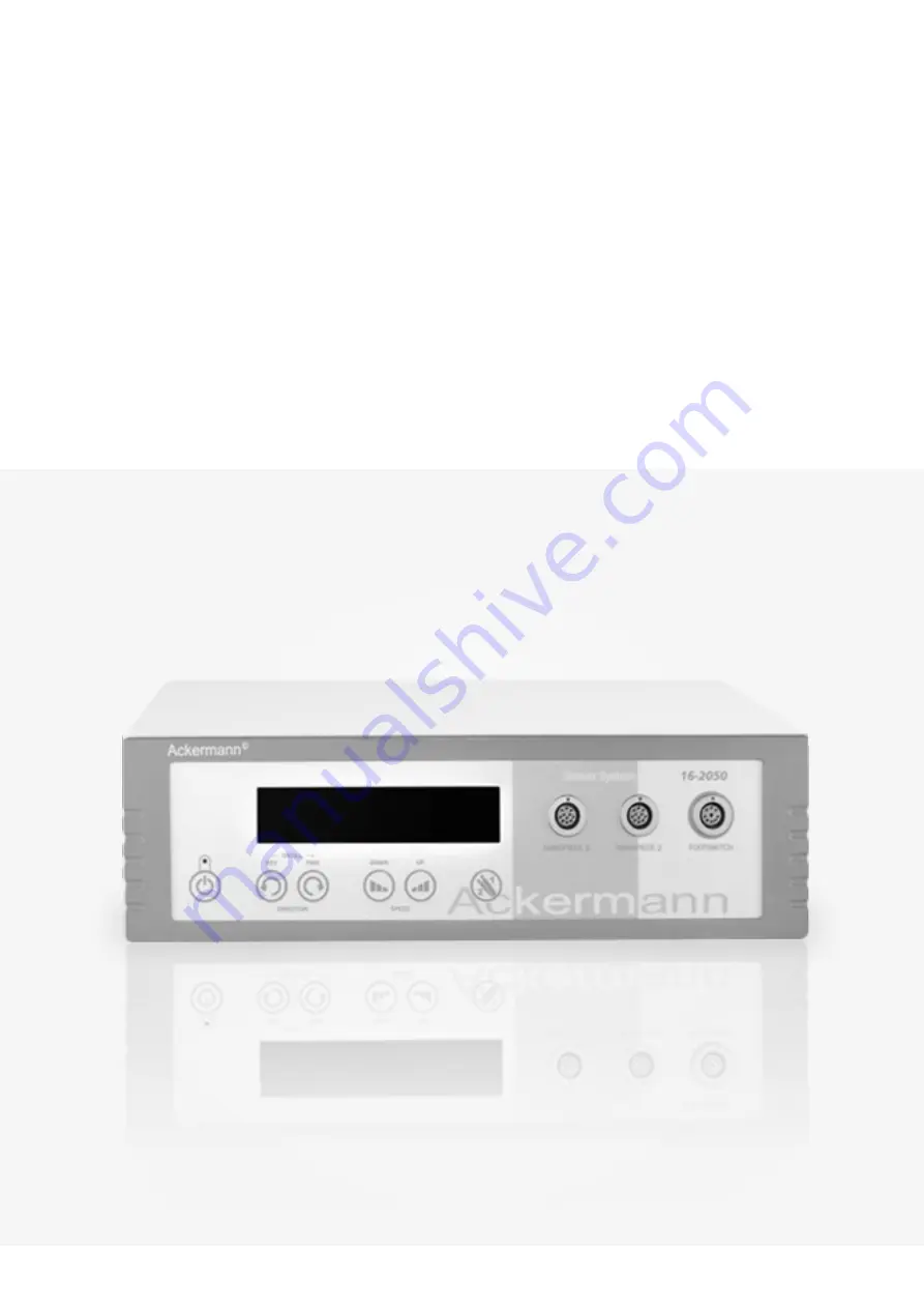
Arthroscopy Shaver System
#16-2050
Handpiece
#16-2050-100
Footswitch
#16-2050-200
User Manual
Page 1: ...SHAVER SYSTEM Ackermann www ackermannsurgical com Arthroscopy Shaver System 16 2050 Handpiece 16 2050 100 Footswitch 16 2050 200 User Manual Arthroscopy Shaver System ...
Page 2: ...ng of the shaver blades 13 5 3 2 Handpiece with manual receiving ring of the shaver blades 13 6 Maintenance and care 13 6 1 General information 14 6 2 Cleaning and disinfection of Control Unit and Footswitch 14 6 3 Cleaning disinfection and sterilization of Handpiece 14 6 3 1 General information 14 6 3 2 Pre cleaning 14 6 3 3 Mechanical cleaning and disinfection 15 6 3 4 Manual cleaning and disinf...
Page 3: ...vice ensurethatadequateventilationisprovidedbeforestartingthedevice Itisrecommended to maintain a min 10cm clearance from the left right and rear sides of the device Under no circumstances open the cover of the device when it is connected to power Electric voltage inside the unit can reach 0 4 kV Electric shock may result in permanent disability or death NEVER place the device near hot surfaces or...
Page 4: ...able 2 Standard package contains Pos Specification Article no Qty 1 Shaver System 16 2050 1 2 Power cord with EU plug n a 1 3 Operating instruction n a 1 4 Spare fuses acc to table 5 2 The device is supplied in a package that should be kept for possible future transport Only proper packing of the device in its original packaging ensures safe transport 2 3 device classification The Shaver System Se...
Page 5: ... General requirements 11 EN 980 Symbols for use in the labelling of medical devices 12 EN 1041 Information supplied by the manufacturer of medical devices 3 description of components 3 1 front panel description 1 Display window displays operating parameters in digital form 2 HANDPIECE 1 socket socket for the Handpiece 1 3 HANDPIECE 2 socket socket for the Handpiece 2 4 FOOTSWITCH socket socket for...
Page 6: ...manufacturing 15 Power switch single pole ON OFF switch used to enable and disable power to the device 16 Power cable socket power cable socket with fuse drawer The nominal values for fuses are specified on the device label Table 5 It is imperative to disconnect the power cord during maintenance cleaning or replacement of fuses 17 Fuse drawer where protecting the device power supply fuses are inst...
Page 7: ...Handpiece 23 Aspiration port when the tube of the vacuum pump is mounted onto this nozzle the saline solution is sucked off through the Handpiece 24 Protective cap for increased stability of the connection between the Handpiece and the cable 25 Cable 3 meters long cable for comfortable attachment to the Control Unit 26 Plug connection to attach the Handpiece to the Control Unit An integrated lock ...
Page 8: ...Shaver system Ackermann Page 8 28 3 4 footswitch description ...
Page 9: ...41 Charging socke used to connect the charger 45 Charging should be done outside of the treatment room While charging functions of the Footswitch are disabled 42 Connection LED flashing on blue diode signals the proper communication between the Footswitch console and the receiver 39 43 Battery charge status LED lighting on green shows the accumulator level 44 Error LED lighting on red diode signal...
Page 10: ...language has been confirmed the next settings can be selected oscillation time and brightness of the VDF display Again the settings are selected by pressing the buttons SPEED DOWN 8 or SPEED UP 9 Confirm settings with the button TOOL 10 The control unit memorizes the settings and automatically returns to normal operating mode 4 3 Connection of Handpiece to Control Unit The plug 26 at the end of th...
Page 11: ...any Bluetooth devices around Proper data transmission is signaled by flashing Connection LED 42 Before starting the work make sure that the accumulator is appropriately charged If the wireless Footswitch console is not connected with the receiver 39 the accumulator level is displayed till the connection with the receiver 39 will be established or till the Footswitch console will be switched to sta...
Page 12: ...ear panel of the Control Unit into ON position Press the STANDBY button 5 upon which the display will switch itself on and perform a brief self test after which the last used settings are reloaded Keyboard the keyboard on the front panel can be used to control all connected Handpieces and to access the language and oscillation mode select menu The additional STANDBY 5 button on the front panel all...
Page 13: ...ocket Push until you can feel resistance Next the lock of receiving ring 20 should be turned the range of 90 The shaver blade is properly engaged when you can hear a clearly audible sound and the instrument cannot be removed even by pulling These activities should be repeated in adverse order to remove the shaver blade from the socket Remove the shaver blade above the operating table only Hold the...
Page 14: ...s have to be strictly observed 6 3 Cleaning disinfection and sterilization of Handpiece 6 3 1 GENERAL INFORMATION Give preference to mechanical cleaning and disinfection of the Handpiece in the washer disinfector Manual reprocessing including ultrasonic bath should only be chosen if mechanical reprocessing is not an option Manual cleaning and disinfection may only take place if the division entity...
Page 15: ...mburg was used The above work flow was determined by the tests in the test laboratory 6 3 3 Mechanical cleaning and disinfection When choosing the washer disinfector make sure that the suitability of the washer disinfector has been proven e g authorized by the FDA or provided with a CE mark pursuant to DIN EN ISO 15883 a program for thermal disinfection is available Ao value 3000 or in older devic...
Page 16: ...n max number of Endo toxin units 0 25 ml e g processed water only The air used for drying must be filtered Work flow 1 Immerse the Handpiece in a bath filled with cleaning disinfectant solution Make sure that the Handpiece is in upright position with the receiving ring 20 facing downwards The Handpiece and the cable must be completely covered with cleaning solution The valve control 21 must be in ...
Page 17: ...ed by an independent test laboratory A sterilizer Selectomat HP 666 1 HRED co MMM Münchener Medizin Mechanik GmbH Planegg Germany was used for the fractionated vacuum and gravitation methods The above work flow was determined by the tests in the test laboratory The Handpiece has to cool down at room temperature Do not use while still warm Accelerated cooling with water or a wet cloth is not permit...
Page 18: ... minutes for disconnecting Replacing fuses is to be performed only if they are damaged Use only such fuses as indicated in Table 5 To replace the fuses remove defective fuses Fuses are located in the drawer 17 installed in the power socket 16 of the device new time delay fuses the values of which should be selected on the basis of Table 5 should be inserted in the slots in the fuse drawer Table 5 ...
Page 19: ...ce partners are authorised to perform them The device is protected from unauthorized opening by the warranty seals A damaged or broken seal voids the warranty and implies to the manufacturer refusing any responsibility for any subsequent malfunctions and or limitations in the functioning of the device the manufacturer s warranty does not cover damage caused by random events such as flooding fall p...
Page 20: ...ontrol Too low battery level in the wireless Footswitch Charge the battery according to recommendations See point 4 5 Connection error between the Footswitch console and the receiv er Re initiatetheconnectionprocedureinaccordancewithparagraph 4 5 4 The Handpiece overheats Issue Solution Prolonged overloading of the Handpiece Remove the Handpiece from the connection socket at the Control Unit and a...
Page 21: ... Unit The CE mark on the device label certifies compliance with all European requirements and with Directive MDD 93 42 EWG Table 8 Handpiece technical specification depending on the device variant Parameter Handpiece Type of Handpiece with manual lock with automatic lock Length 180 g 184 g Weight 400 g without cable Speed 800 8000 rpm 10 Oscillation frequency Slow 0 5 s normal 0 3 s fast 0 2 s Cab...
Page 22: ...orage and transport 90 Protection against harmful ingress of water or particulate or particulate matter IP X8 Protection against the effects of continuous immersion in water The CE mark on the device label certifies compliance with all European requirements and with Directive MDD 93 42 EWG 9 SYMBOLS and markings 9 1 SYMBOLS USED ON LABELLING Table 10 Summary of symbols and their meanings Symbol an...
Page 23: ...rent EU wide legislation implemented in each member state requires that all electrical and electronic Equipment marked with this symbol is disposed separately of other waste This includes electronic devices or electrical accessories such as cables electronics etc When disposing of such products please follow the advice of your local authorities The symbol shown on electrical and electronic product...
Page 24: ...pply lines 1 kV for input output lines Lack of visible influence on device The device is treated as a single component no wires in out Mains power quality should be that of a typical commercial or hospital environment Surge IEC 61000 4 5 2 kV line toground 1 kV line to line Lack of visible influence on device Mains power quality should be that of a typical commercial or hospital environment Voltag...
Page 25: ...electromagnetic site survey a should be less than the compliance level in each frequency range b Interference may occur in the vicinity of equipment marked with the following symbol NOTE 1 At 80 MHz and 800 MHz the higher frequency range applies NOTE 2 These guidelines may not apply in all situations Electromagnetic propagation is affected by absorption and reflection from a Fidel strengths from f...
Page 26: ...Prms 80 kHz to 800 MHz d 1 16 Prms 800 kHz to 2 5 GHz d 2 33 Prms 0 01 0 12 0 12 0 23 0 1 0 37 0 37 0 74 1 1 16 1 16 2 33 10 3 67 3 67 7 36 100 11 6 11 6 23 3 Fortransmittersratedatamaximumoutputpowernotlistedabove therecommendedseparationdistancedinmeters m canbeestimated using the equation applicable to the frequency of the transmitter where P is the maximum output power rating of the transmitte...
Page 27: ...EM 12 CONTACT DETAILS Ackermann Instrumente GmbH Eisenbahnstrasse 65 67 78604 Rietheim Weilheim Germany Phone 49 0 7461 966 17 0 Fax 49 0 7461 966 17 70 E Mail sales ackermannsurgical com Web www ackermannsurgical com End of document ...
Page 28: ...ietheim Weilheim Germany User_Manual 16 2050 Revision_05 21 Copyright by Ackermann Instrumente GmbH Specifications design and accessories in this user manual are subject to change without any notice or obligation on the part of the manufacturer Ackermann 0483 ...