background image

60 


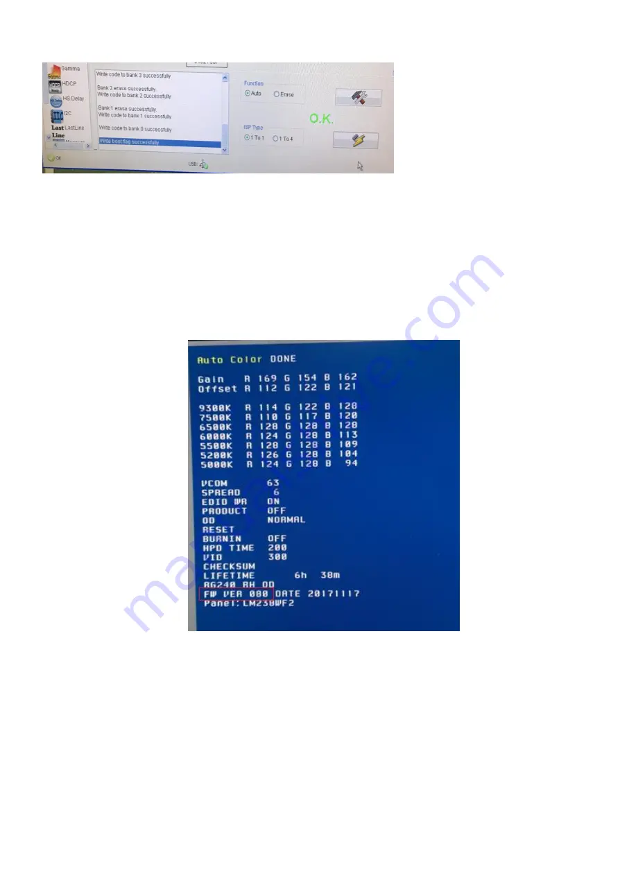
6.4 How to check firmware version 

S1. Power off t

he monitor, press “Power” and “down key“of navi key at the same time to power on the monitor. 

S2. Press any key except power key to show hot key menu, then press hot key1 to enter factory menu. You will see 

the firmware version on the screen. 

Note: Please pay attention: Don

’t change any parameter which is measured by precise machine before shipping out. 


Summary of Contents for X34GS

Page 1: ...1 ACER_X34GS LIFECYCLE EXTENSION GUIDE ...

Page 2: ... 36 03 Exploded Diagram 46 04 Wiring connectivity diagram 47 05 Mechanical Instruction 47 06 Assembly and Disassembly Procedures 48 07 Trouble shooting 55 08 Firmware Upgrade Procedure 58 09 Writing EDID Procedure 61 10 SN Writing Process 64 11 FRU Field Replaceable Unit List 66 12 Timing table 69 ...

Page 3: ...mize the risk of personal injury when perform service procedures Furthermore the possible existed improper repairing method may damage equipment or products It is recommended that service engineers should have repairing knowledge experience as well as appropriate product training per new model before performing the service procedures NOTICE To avoid electrical shocks the products should be connect...

Page 4: ... element shall be a 34 inch diagonal WQHD 3440x1440 resolution TFT LCD display Thin Film Transistor Liquid Crystal Display and support Video input signals are two HDMI two DP with non interlaced signal Power saving function complies with the VESA DPMS Display Power Management Standard And support 1ms VRB General display parameters Lehui 34 panel LM340UW6 SSA3 ...

Page 5: ...5 ...

Page 6: ...l white pattern The warm up time is more than 30 minutes Ambient light should be less than 1 Lux 1 2 2 Test Equipment The reference signal source is a calibrated Chroma 2326 or Quantum 801GD video generator The use of compatible generators during qualification and production is acceptable Luminance meter is Minolta CA210 TOPCON BM7 or compatible equipment ...

Page 7: ...7 ACER S190HQL 3 1 3 Electrical This section describes the electrical requirement of the pure A H DP monitor Below is the pure X34GS monitor s block diagram X34GS bmiippruzx ...

Page 8: ...Jack WAFER 2 5mm 4P 90 DIP Input connectors HDMI 19pinx2 DisplayPort 20 pin x 2 Type B 3 0 9 pin x1 Type C 12 pinx1 Type A 18 pinx4 Power Consumption 100 240 Vac 50 60Hz 180W max Power Saving 0 5W Power Off 0 3W User s Cont rol Buttons POWER hotkey1 hotkey2 inputkey menukey Dimming control range max min max x 100 100 Pre Defined Timing Preset Timing 15 User s Timing 16 Plug and Play VESA DDCCI Pow...

Page 9: ...ol 7 NC 8 NC B Backlight connector D HDMI connector Pin Signal Assignment Pin Signal Assignment 1 TMDS Data2 2 TMDS Data2 Shield 3 TMDS Data2 4 TMDS Data1 5 TMDS Data1 Shield 6 TMDS Data1 7 TMDS Data0 8 TMDS Data0 Shield 9 TMDS Data0 10 TMDS Clock 11 TMDS Clock Shield 12 TMDS Clock 13 CEC 14 Reserved N C on device 15 SCL 16 SDA 17 EDID CEC Ground 18 5V Power ...

Page 10: ...e 2 p Lane 2 positive 8 GND Ground 9 ML_Lane 2 n Lane 2 negative 10 ML_Lane 3 p Lane 3 positive 11 GND Ground 12 ML_Lane 3 n Lane 3 negative 13 CONFIG1 connected to Ground1 14 CONFIG2 connected to Ground1 15 AUX CH p Auxiliary Channel positive 16 GND Ground 17 AUX CH n Auxiliary Channel negative 18 Hot Plug Hot Plug Detect 19 Return Return for Power 20 DP_PWR Power for connector 3 3 V 500 mA Type ...

Page 11: ...11 Type A 3 0 Connect 針腳編號 顏色 訊號 Type A 訊號 Type B 1 紅色 VBUS 2 白色 D 3 綠色 D 4 黑色 GND 5 藍色 StdA_SSRX StdB_SSTX ...

Page 12: ...12 6 黃色 StdA_SSRX StdB_SSTX 7 Shield GND_DRAIN 8 紫色 StdA_SSTX StdB_SSRX 9 橙色 StdA_SSTX StdB_SSRX Type C Connector Input signal connector of LVDS ...

Page 13: ... Red Green and Blue signals each has its own coaxial cable terminated at the monitor These video signals are analog levels where 0V corresponds to black and 735mV is the maximum signal amplitude for the respective color The video signal is terminated with 75 ohms ...

Page 14: ...at is the input level at which the monitor actually detects a logic 0 shall be at least 0 3 volt lower than the level at which it actually detects a logic 1 If the monitor sync processing circuits were designed with 3 3 volt logic family then the sync inputs must be 5 volt tolerant 1 3 2 5 Sync Signal Loading TTL input loading shall be equivalent to one TTL input load When logic 0 is asserted by a...

Page 15: ...or LED The monitor shall have LED indicators located on the head of the monitor Table 1 is the LED color for the power indicator LED light Status Remark Off AC power Off Key Off power cord removed Key Off Blue Power on OSD working Amber standby power saving 1 3 3 3 Key definition 1 3 3 4 Key Function Overview All functions are controlled by OSD buttons on the head of the monitor ...

Page 16: ...een parameters can be adjusted by the front bezel control buttons and then saved as a user defined mode The monitor shall include all the preset video timings shown in the following table 1 3 5 Controller Requirements 1 3 5 1 General Requirements The monitor shall include a controller which is capable of converting the analog RGB signal or HDMI digital signal to the panel The controller will inclu...

Page 17: ...cation of an input voltage below the minimum specified in this table shall not cause damage to the power adaptor unit nor cause failure of the input Line Transient The power adaptor shall operate within EN 61000 4 4 1KV and EN 61000 4 5 2KV The power adaptor shall operate and comply with CE mark 1 3 7 Display Communications Channel The monitor shall provide a display communications channel that co...

Page 18: ...ge shall be 90 degrees Horizontal and 65 degrees vertical typically Defects not apparent within one minute shall be ignored 1 4 5 5 Defect Terminology Dark Spots Lines Spots or lines that appear dark in the display patterns and are usually the result of contamination Defects do not vary in size or intensity contrast when contrast voltage is varied Contrast variation can be achieved through the use...

Page 19: ... It shall be test at 1366x768 60Hz mode and full white full black square pattern with contrast brightness in default value The values specified are at an approximate distance 50cm from the LCD surface and at 0 viewing angle The contrast ratio is calculated as below Surface luminance with all white pixels Contrast ratio CR Surface luminance with all black pixels 1 5 2 2 ACM Auto Contrast Management...

Page 20: ...x1080 60Hz Full White pattern Brightness Contrast in default setting The x and y co ordinates for Reddish Bluish and User preset mode shall be as below Color Coordinate Mode Color Coordinates CIE 1931 White x White y Percent of Panel Max brightness Brightness OSD value Contrast OSD value Slope ratio for the gamma 80 0 32 0 03 0 35 0 03 80 80 50 1 ...

Page 21: ...creen after at least 30 minutes warm up It shall be test at 1920x1080 60Hz mode and the brightness and contrast OSD setting for 100 The values specified are at an approximate distance 50 cm from the LCD surface and at 0 viewing angle The full screen white center luminance at User mode color temperature shall be 250 cd m typ And 200 cd m min Full screen black pattern luminance at center should be 1...

Page 22: ...22 ...

Page 23: ...23 ...

Page 24: ...24 ...

Page 25: ...25 ...

Page 26: ...26 ...

Page 27: ...27 ...

Page 28: ...28 ...

Page 29: ...29 ...

Page 30: ...30 ...

Page 31: ...31 ...

Page 32: ...32 ...

Page 33: ...33 ...

Page 34: ...ss than 70 1 7 Mechanical and Packing Packaged Dimensions a Height 560 3 mm b Width 685 3 mm c Depth 375 3 mm Pallet Load By Sea a 20 GQ 9units pallet b 40 GQ 9units pallet Container Load a 20 container GQ 108units 9 x 12 pallets b 40 container GQ 234units 9 x 26 pallets Dimension mm ...

Page 35: ...5 Note If installing with a wall mounting kit it is recommended to use VESA mounting kit 100mm x 100mm with M4 x 10 L mm screws to fix your monitor on the wall The Distance of hole of wall mount as below ...

Page 36: ...Key Menu 1 Display Function Menu while user press any function button 2 Layout as following figure 2 3 Main Menu 2 3 1 OSD layout a Display OSD menu when user press Navi Key button b Layout as following figure Picture Color ...

Page 37: ...37 Audio Gaming ...

Page 38: ...38 OSD System ...

Page 39: ...39 Information Save settings to ...

Page 40: ...40 c Icons introduct d Item page status 2 3 2 Key operation ...

Page 41: ...41 ...

Page 42: ...election Open the Mode control and turn Mode on or off using the adjustment arrows OFF ON and select which profile to use 2 5 Acer logo When the monitor is power on the Acer G sync LOGO will be showed 2 6 OSD Message ...

Page 43: ...43 ...

Page 44: ...44 2 7 OSD Menu Tree ...

Page 45: ...45 ...

Page 46: ...46 3 Exploded Diagram ...

Page 47: ... use by end of life recyclers or treatment facilities It provides the basic instructions for the disassembly of Acer products to remove components and materials requiring selective treatment 1 0 Tools Required List the type and size of the tools that would typically be used to disassemble the product to a point where components and materials requiring selective treatment can be removed Tool Descri...

Page 48: ...2 OPTIONAL Depending upon the complexity of the disassembly process a graphic depicting the locations of items contained within the product which require selective treatment with descriptions and arrows identifying locations can be inserted below 6 Assembly and Disassembly Procedures Disassembly Procedur Step 1 Pull the Vesa Cover out by screwdriver Step 2 Unscrew four screws then pull out the sta...

Page 49: ...49 Step 3 Separate hooks between MID_FRAME and R C Step 4 Pull up the Rear Cover pull out all connectors and light sensor board Step 5 Separate SPK from MID_FRAME ...

Page 50: ...50 Step 6 Unscrew 9 screws and overturn main shielding pull out the connector Step 7 Unscrew 2 screws then pull out the main board from shielding Step 8 Remove all connecters and pull out push pin ...

Page 51: ... 9 Unscrew 20 screws and separate MID FRAME and LCM Step 10 Separate lens from MID frame Step 11 Unscrew 3 screws and disassemble key board from rear cover and separate navi key cable and remove all connectors ...

Page 52: ...than assembly shielding cover and shielding use screw to fix Assembly main board on LCM Step2 Insert 60 pin LVDS FFC and Wireharness to LCM Step3 Lock the shielding on panel with screw Use shielding AL tape fix edp cable and sheilding Step4 Lock middle frame screw ...

Page 53: ...3 Step5 Assembly USB BD on the mid frame and use screw lock it insert 30 pin FFC connect MB and USB BD Step6 Fix the speak in the mid frame and connect the Speak wire to the MB use tape to fix speak wire ...

Page 54: ...pin FFC to MB Step8 Assembly Key BD and LED BD in the rare cover insert 6pin FFC to MB use tape to fix it Step9 Assembly rear cover and push around the surrounding to make sure assembly well Step10 Put in stand and use 4 screw lock it than clip into VESA Cover ...

Page 55: ... into AC source AC power Check adaptor Key s LED indicator is light or blink No input signal BLACK screen but a little light Re insert 30pin LVDS cable between LCM and main board Still BLACK screen 5VD_REG 3V3D_REG and 1VD_REG on main board is normal Check Main board LCM broken END N Y blink light Y N ...

Page 56: ...y Debug Replace keyboard Check U12 works END N Y Key works Disconnect LVDS cable Replace panel Check set is ok Check U12 works N Y Check LCM power R82 5V ok Check Q1 pin2 is 5V N N Y Check Q2 pin2 is high 2 4V LCM power Debug Y N Y Replace Q1 END ...

Page 57: ... 19V Replace FB36 FB36 is open BD4 is damaged BU3 is damaged Replace BU3 Check U12 works END N Y Y N Y N Replace BD4 Backlight on Y N BR31 is open Replace BR31 Y N Open BR67 Y N Check BU5 pin5 is high Check NET BL_CTRL level is high Reassemble BR67 Y N Y Y N Replace BU5 ...

Page 58: ...s must be ready in progress 6 1 1 Hardware Required X34GS set 1pcs PC with Windows HDMI cable 1pcs USB cable 1pcs X34GS set 1 pcs Realtek ISP Board 1 pcs P N 352300120184 DP Cable or HDMI Cable 1pcs USB Cable 1 6 1 2 Software Preparation Realtek ISP TOOL V3 6 Latest firmware binary files 6 2 Hardware Configuration ...

Page 59: ...h RTD Customer Tool S2 Select ISP option Select Setting ICON Erase Setting select Bank Erase S3 Click ICON to the F W bin you want to update S4 Make sure the USB Connection is OK Flash FW by button S5 After update successful it will display OK ...

Page 60: ...ey at the same time to power on the monitor S2 Press any key except power key to show hot key menu then press hot key1 to enter factory menu You will see the firmware version on the screen Note Please pay attention Don t change any parameter which is measured by precise machine before shipping out ...

Page 61: ...ory Mode EDID WR set OFF refer to section 7 3 A 7 2 EDID Generator Operation Notice X34GS hadn t EEPROM for VGA port The VGA EDID was included in flash User can select Bank Erase to update firmware Then VGA EDID will restore default value S1 RTD TOOL Click New EDID S2 Press Load button and select the binary file which is prepared to update S3 Press Write Button to write EDID data ...

Page 62: ... How to Entery Facotory Mode A Entery Facotory Mode by i Press Power Key Down Key of navi key to Power on ii Select F Item in Hot key Menu Figure 1 Hot key Menu with Factory Mode Enabled Figure 2 Factory Menu ...

Page 63: ...onitor The burn in mode has been turn off already If DC off failed please go to step 2 Step 2 If power key is unusable send a HDMI signal to the monitor to make sure it can show what you have sent Then press the power key to DC off and DC on the monitor The burn in mode has been turn off already Remark 1 VGA signal with VGA port model HDMI signal without VGA port model ...

Page 64: ...with Windows HDMI cable 1pcs Launch softMCCS as below Follow below steps to execute DDCCI command 1 Select Monitor X34GS 2 Check Supported is enable for DDCCI successful connection 3 Press this button to open command window 1 Select Monitor X34GS 2 Check Supported for DDCCI successful connection ...

Page 65: ...R004102000702400 Command format as following C0 63 07 6B 45 54 4C 54 4B 30 52 30 30 34 31 30 32 30 30 30 37 30 32 34 30 30 Blue command header Red The ASCII code transfer from SN Confirmation the return code is E0 after execution command ...

Page 66: ...66 11 FRU Field Replaceable Unit List ...

Page 67: ...67 ...

Page 68: ...68 12 Timing table Mode Resolution active dot Resolution total dot Horizontal Frequency KHz Vertical Frequency Hz Nominal Pixel Clock MHz ...

Page 69: ...600x900 67 500 75 000 108 000 1280x960 60Hz 1800x1000 60 000 60 000 108 000 SXGA 1280x1024 60Hz 1688x1066 63 981 60 020 108 000 1280x1024 75Hz 1688x1066 79 976 75 025 135 000 VESA 1280x720 60Hz 1650x750 45 000 60 000 74 250 WXGA 1280x800 60Hz 1680x831 49 702 59 810 83 500 WXGA 1440x900 60Hz 1904x934 55 935 59 887 106 500 WSXGA 1680x1050 60Hz 2240x1089 65 290 59 954 146 250 FHD 1920x1080 60Hz 2200x...

Page 70: ...0 45 000 60 00 74 250 16 1920x1080p 16 9 59 94 67 433 59 94 148 352 60 67 500 60 00 148 500 17 720x576p 4 3 50 31 250 50 00 27 000 18 720x576p 16 9 50 31 250 50 00 27 000 19 1280x720p 16 9 50 37 500 50 00 74 250 31 1920x1080p 16 9 50 56 250 50 00 148 500 32 1920x1080p 16 9 23 97 26 973 23 97 74 176 24 27 000 24 74 250 33 1920x1080p 16 9 25 28 125 25 00 74 250 34 1920x1080p 16 9 29 97 33 716 29 97 ...

Reviews: