


123
Chapter 7
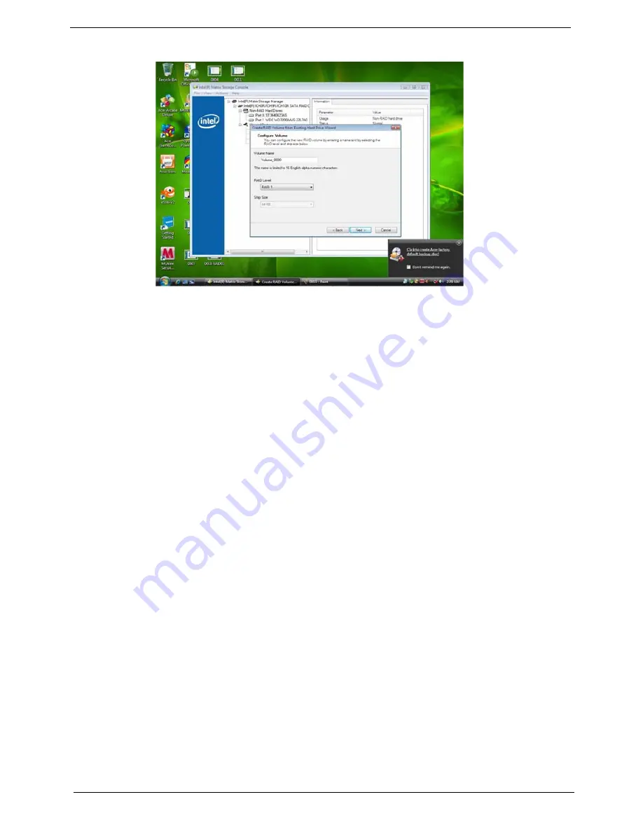
Step 6:Key the name in "Volume Name" and select "RAID 1" in RAID Level.
Picture10
Step 7:Select minimum HDD as "Source Hard Drive".
Step 8:Select Menber Hard Drive(s).
Step 9:Specify Volume Size then press "next".
Step 10:Press "next" to finish setup and start create RAID1.
Step 11:It may takes half and hours to create RAID1.After create completely,it will ask to reboot to finish create
RAID1.
2-3:Create a“RAID Ready” System into" RAID 5" with three Hard Drives by‘Create RAID Volume
from Existing HDD Drive ’.
Step 1:Install WIN7 OS with one SATA HDD.
Step 2:Shut down the system,then add other two serial ATA hard drives in the system.
Step 3:Boot to OS desktop, open the Intel® Matrix Storage Console.
Step 4:Click on the by‘Create RAID Volume from Existing HDD Drive ’ to create a RAID volume.
Step 5:Click "Next" at create a RAID volume window.
Step 6:Key the name in "Volume Name" and select "RAID 1" in RAID Level.
Summary of Contents for Veriton M6618G
Page 1: ...Acer Veriton M6610 M6610G M6618G Service Guide PRINTED IN TAIWAN...
Page 14: ...6 Chapter 1 Block Diagram...
Page 69: ...Chapter 3 61 Install the I O Shielding 1 Install I O shielding into chassis...
Page 71: ...Chapter 3 63 4 Connect the ATX 24Pin Power cable and ATX 4Pin Power cable to main board...
Page 72: ...64 Chapter 3 Install the System FAN 1 Tie system fan cable 2 Push the system fan to chassis...
Page 73: ...Chapter 3 65 3 Fix the four screws 4 Connect the system fan power cable to Main board...
Page 78: ...70 Chapter 3 5 Close the lock handle IMPORTANT Install the 3 5 Card rule...
Page 84: ...76 Chapter 3 Install the Right Side Panel 1 Install the side Panel then fix two Screws...
Page 85: ...Chapter 3 77 Install the VGA Card 1 Remove the PCI fixer 2 Remove the PCI slot...
Page 86: ...78 Chapter 3 3 Open the VGA card latch then press down the VGA card 4 Close the PCI fixer...
Page 96: ...Chapter 5 88 M B Placement Jumper and Connector Information Chapter 5...
Page 129: ...121 Chapter 7 Picture6 Step 8 Select Menber Hard Drive s Picture7...


