background image

                                                                                                                                                           71

9.

Detach the modem card from the main board.

10.

Disconnect the one button recovery connector, chassis intrusion switch connector, front panel connectors, 
and system fan connector from the main board.

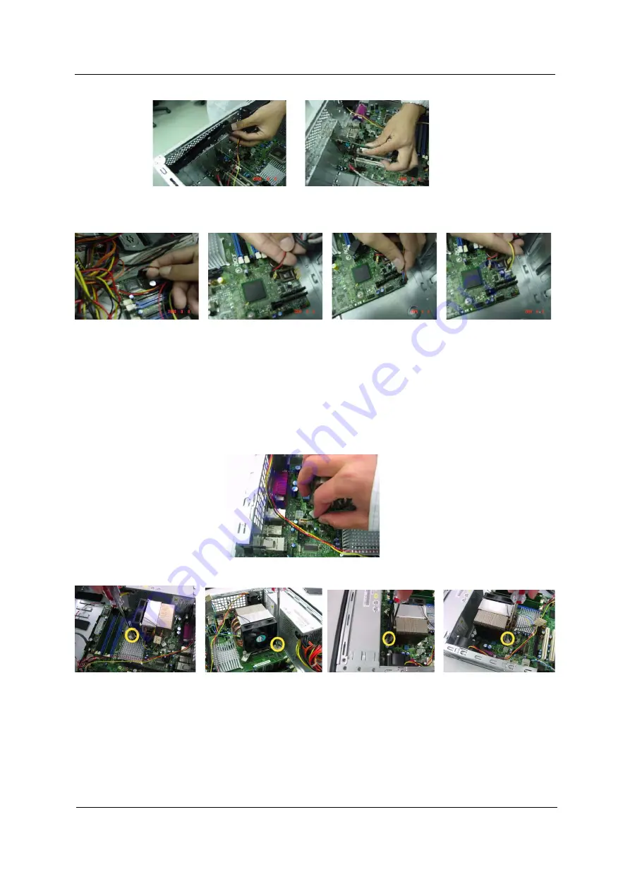
Removing the CPU Fan Sink, CPU and System Fan

1.

Disconnect the CPU fan connector from the main board.

2.

Remove thefour screws on both side of the fan sink.

Summary of Contents for Veriton 3700G

Page 1: ...Veriton 7700G 5700G 3700G Service Guide PRINTED IN TAIWAN Service guide files and updates are available on the AIPG CSD web for more information please refer to http csd acer com tw ...

Page 2: ...Revision History Please refer to the table below for the updates made on Veriton 7700G 5700G 3700G service guide Date Chapter Updates 12 17 2004 Ch2 System Utilities Add information about the hidden pages ...

Page 3: ...espect to the contents hereof and specifically disclaims any warranties of merchantability or fitness for any particular purpose Any Acer Incorporated software described in this manual is sold or licensed as is Should the programs prove defective following their purchase the buyer and not Acer Incorporated its distributor or its dealer assumes the entire cost of all necessary servicing repair and ...

Page 4: ... bits and pieces of additional information related to the current topic WARNING Alerts you to any damage that might result from doing or not doing specific actions CAUTION Gives precautionary measures to avoid possible hardware or software problems IMPORTANT Reminds you to do specific actions relevant to the accomplishment of procedures ...

Page 5: ... NOT be covered in this generic service guide In such cases please contact your regional offices or the responsible personnel channel to provide you with further technical details 2 Please note WHEN ORDERING FRU PARTS that you should check the most up to date information available on your regional web or channel If for whatever reason a part number change is made it will not be noted in the printe...

Page 6: ...tup 46 Exit Without Saving 47 Chapter 3 Machine Disassembly and Replacement 48 General Information 49 VT 3700G Disassembly Flow Chart 50 Standard Disassembly Procedure 51 VT 5700G Disassembly Flow Chart 59 Standard Disassembly Procedure 60 VT 7700G Disassembly Flow Chart 67 Standard Disassembly Procedure 68 Chapter 4 Troubleshooting 75 Power On Self Test POST 76 POST Error Messages List 82 Error S...

Page 7: ...G ICH6 chipset Architecture and Intel Pentium 4 Socket T can run at 800MHz FSB which gives more performance than other processors It also provide 1 PCI Express x 16 slot for add on graphic solution 1 PCI Express x 1 slot and 2 PCI slots support PCI 2 2 spec 4 Dual channel DDR1 memory slot support up to 4GB two parallel ATA device four serial ATA devices hard drive disks and on board Gigabit LAN on...

Page 8: ...t Headphone Out front T S N ration 90 dB at output jack T Support internal speaker NOTE The system has two microphone in jacks front and rear Connectivity T Two conventional PCI 2 2 5V slots one PCI Express x16 slot and one PCI Express interface T Support HDD CD ROM CD RW DVD ROM DVD RW DVD RW DVD Dual or DVD Supermultiplus storage type T Four SATA IDE slot and one PATA IDE slot T Supports USB 2 0...

Page 9: ...en Suspend Orange T One single color LED for HDD Green T One single color LED for LAN Active Link Green T One Power Switch Hardware Monitor T Controller SMSC LPC47M182 NR Management ASIC Heceta 6e T Monitor CPU System temperature T Monitor CPU FAN speed T Monitor Voltage ...

Page 10: ...ter 1 Front Panel for Veriton 3700G The computer s front panel consists of the following Label Icon Description 1 Floppy drive LED 2 Floppy drive eject button 3 Optical drive Stop Eject Button 4 Power button ...

Page 11: ...system has two microphone in ports front and rear 5 Power LED 6 LAN activity LED 7 Hard disk drive activity LED 8 One button recovery slot 9 USB ports 10 Headphone out port 11 Microphone in port front Label Icon Description ...

Page 12: ...6 Chapter 1 Rear Panel for Veriton 3700G ...

Page 13: ...et Connect the monitor to the VGA port instead Label Icon Color Description 1 White Network port 2 Black USB ports 3 Black USB ports 4 Light blue Audio in Line in jack 5 Lime Audio out Line out jack 6 Pink Microphone in jack rear 7 Blue CRT LCD monitor port 8 Burgundy Parallel printer port 9 Teal or Turquoise Serial port 10 Purple PS 2 keyboard port 11 Green PS 2 mouse port 12 Power cord socket ...

Page 14: ...puter s front panel consists of the following Label Icon Description 1 Floppy drive eject button 2 Floppy drive LED 3 One button recovery slot 4 Headphone out port 5 Microphone in port front 6 USB ports 7 Power button 8 Optical drive Stop Eject Button ...

Page 15: ...Chapter 1 9 NOTE The system has two microphone in ports front and rear 9 Power LED 10 LAN activity LED 11 Hard disk drive activity LED 12 Optical drive Stop Eject Button Label Icon Description ...

Page 16: ... Description 1 White Network port 2 Black USB ports 3 Black USB ports 4 Pink Microphone in jack rear 5 Lime Audio out Line out jack 6 Light blue Audio in Line in jack 7 Blue CRT LCD monitor port 8 Burgundy Parallel printer port 9 Teal or Turquoise Serial port ...

Page 17: ...OTE The CRT monitor port is automatically disabled when an add on VGA card is installed into the system for Intel 915G chipset Connect the monitor to the VGA port instead 10 Purple PS 2 keyboard port 11 Green PS 2 mouse port 12 Power cord socket Label Icon Color Description ...

Page 18: ...12 Chapter 1 Front Panel for Veriton 7700G The computer s front panel consists of the following Label Icon Description 1 USB ports 2 Microphone in port front 3 Speak out line out port ...

Page 19: ...front and rear 4 Optical drive Stop Eject Button 5 Optical drive Stop Eject Button 6 Floppy drive LED 7 Floppy drive eject button 8 One button recovery slot 9 Power button 10 Power LED 11 LAN activity LED 12 Hard disk drive activity LED Label Icon Description ...

Page 20: ...14 Chapter 1 Rear Panel for Veriton 7700G Label Icon Color Description 1 White Network port 2 Black USB ports 3 Black USB ports ...

Page 21: ...lled into the system Connect the monitor to the VGA port instead 4 Light blue Audio in Line in jack 5 Lime Audio out Line out jack 6 Pink Microphone in jack rear 7 Blue CRT LCD monitor port 8 Burgundy Parallel printer port 9 Teal or Turquoise Serial port 10 Purple PS 2 keyboard port 11 Green PS 2 mouse port 12 Power cord socket Label Icon Color Description ...

Page 22: ...Intel 82562EX 82562EZ x1 PCI Express Primary ATA IDE Dual Channel DDR 333 400 800 MT s AC 97 Azalia Audio Codec Multiplexed Mic In Center or Sub woofer Line in or Rear CD Rom Line out or Front SMBus SMBus PCI Express x16 PCI Express TPM 1 1 SIO Integrated Graphics VGA Output SATA port 3 SATA port 2 SATA port 1 SATA port 0 DDR PCI Slot 2 PCI Slot 1 PS 2 DDR Fan control and monitoring USB 2 0 USB 2 ...

Page 23: ...led with your system Search opens a search window 3 Multimedia keys Allow you to do the following Play Pause button press to start playing the audio track or video file Press again to pause Stop button press to stop playing the audio track or video file Forward button press to skip forward to the next track or file and start playing Backward button press to skip backward to the previous track or f...

Page 24: ...Opens the applications context menu same function as clicking the right button of the mouse 9 Windows logo key Start button Combinations with this key perform special functions such as Windows Tab Activates the next Taskbar button Windows E Explore My Computer Windows F Find Document Windows M Minimize All j Windows M Undo Minimize All Windows R Displays Run dialog box 10 Caps lock When activated ...

Page 25: ...y Item Specification Memory socket number 4 sockets Support memory size per socket 128 256 512 1024MB Support maximum memory size 4GB 4096MB Support memory type Dual Channel DDR Support memory speed DDR 333 DDR 400 Support memory voltage 2 5V Support memory module package 184 pin DIMM Support to parity check feature Yes Support to Error Correction Code ECC feature No Memory module combinations You...

Page 26: ...atibility High Definition Audio compliant EAX 1 0 2 0 compatible A3D compatible I3DL2 compatible Direct Sound 3D compatible Mixed digital and analog high performance chip Enhanced stereo full duplex operation Meets performance requirements on PC 99 2001 systems Meets WHQL WLP 2 0 audio requirements Sampling rate 96KHz MPU 401 UART support Yes Microphone jack Front Panel Rear Panel Access Headphone...

Page 27: ...type female connector Parallel port function control Enable disable by BIOS Setup Optional ECP DMA channel in BIOS Setup DMA channel 1 DMA channel 3 Optional parallel port I O address via BIOS Setup 378 37F 278 27F 778 77A Optional parallel port IRQ via BIOS Setup IRQ5 IRQ7 Serial Port Item Specification Serial port controller Embedded in SMSC LPC 47M182 NR Serial port controller resident bus LPC ...

Page 28: ...ng at 40 C Electrostatic Discharge Susceptibility ESD Air Discharge 4kV 4kV No error 8kV 8kV No restart error damage error 15kV 15kV No damage error Contact Discharge 4kV 4kV No error 6kV 6kV No restart error damage error 8kV 8kV No damage error Vibration test criteria operating 5 16 2 Hz 0 38mm peak to peak 16 2 250 Hz 0 2G Sweep rate 1 octave minute Direction X Y Z axis Test cycles 2 cycles per ...

Page 29: ...V 3 Support both PFC Non PFC 1 Design for Intel Grantsdale ICH6 series chipset system 2 Voltage covered 5V 3 3V 12V 5VSB 12V 3 Support both PFC Non PFC Acoustic criteria Item 7700G 5700G 3700G Operator Idle mode 35dBA or under under Windows OS 35dBA or under under Windows OS 35dBA or under under Windows OS Bystander Idle mode 30dBA or under under Windows OS 30dBA or under under Windows OS 28dBA or...

Page 30: ...guration values into the battery backed nonvolatile memory called CMOS RAM This memory area is not part of the system RAM NOTE If you repeatedly receive Run Setup messages the battery may be bad In this case the system cannot retain configuration values in CMOS Before you run Setup make sure that you have saved all open files The system reboots immediately after you exit Setup System Utilities Cha...

Page 31: ...rameter setting press or until the desired setting is found or press e to pop out the screen with available items for selection Press to return to the main menu If you are already in the main menu press again to exit Setup The parameters on the screens show default values These values may not be the same as those in your system The grayed items on the screens have fixed settings and are not user c...

Page 32: ...r Description Advanced Chipset Features Allows configuration of advanced chipset settings such as memory timings etc Both auto configuration and manual configuration oprions are available PnP PCI Configuration Allows configuration of PCI slot IRQ assignments and Latency Timers Fan Control Fan settings can be adjusted through this menu Parameter Description X X X X X X X IJKL XProduct Information X...

Page 33: ...elect Product Information from the main menu The Product Information menu contains general data about the system such as the product name serial number BIOS version etc These information is necessary for troubleshooting maybe required when asking for technical support ...

Page 34: ...Chapter 2 28 ...

Page 35: ... s identification number SMBIOS Version The System Management Interface SM BIOS allows you to check your system hardware components without actually opening your system Hardware checking is done via software during start up This parameter specifies the version of the SMBIOS utility installed in your system System BIOS Version Specifies the version of your BIOS utility System BIOS Release Date Disp...

Page 36: ...DE Channel 0 Master Lets you configure the hard disk drive connected to the master port of IDE channel 0 To enter the IDE Channel 0 Master setup press e The IDE CD ROM is always automatically detected Show the Status None HDD or CD ROM Number IDE Channel 0 Slave Lets you configure the hard disk drive connected to the slave port of IDE channel 0 To enter the IDE Channel 0 Slave setup press e The ID...

Page 37: ...ly detected Show the Status None HDD or CD ROM Number Floppy A Allows you to configure your floppy drive A 1 44 MB 3 5 inch None 360 KB 5 25 inch 1 2 MB 5 25 inch 720 KB 3 5 inch 2 88 MB 3 5 inch Halt On This parameter enables you to control the system stops in case of Power on self test POST errors All But Keyboard All Errors No Errors All But Diskette All But Disk Key Parameter Description Optio...

Page 38: ...ve The following screen appears if you select any of the IDE drive parameters The following table describes the parameters found in this menu Parameter Description Options IDE HDD Auto Detection Auto detects your hard disk drive Press Enter ...

Page 39: ...r data transfers are enabled This item is read only unless Type is set to User Disabled Auto PIO Mode Sets the PIO mode This item is read only unless Type is set to User Auto 0 1 2 3 4 DMA Mode Specifies the DMA mode for the drive Auto Auto SWDMAn Single Word DMAn MWDMAn Multi Word DMAn UDMAn Ultra DMAn This item is read only unless Type is set to User Auto SWDMA0 SWDMA1 SWDMA2 MWDMA0 MWDMA1 MWDMA...

Page 40: ... show a warning message on screen and alarm beep Disabled Enabled Slient Boot Disabled displays normal POST messages Enabled displays OEM graphic instead of POST messages Disabled Enabled Quick Power On Self Test This parameter speeds up POST by skipping some items that are normally checked Enabled Disabled First Boot Device This parameter allows you to specify the system boot up search sequence F...

Page 41: ...rst 64KB of extended memory When the default value Fast is selected the Gate A20 is controlled by port 92 or chipset specific method resulting in faster system performance When Normal is selected A20 is controlled by a keyboard controller or chipset hardware Fast Normal APIC Mode This field is used to enable or disable the APIC Advanced Programmable Interrupt Controller Due to compliance with PC20...

Page 42: ...SB 2 0 driver installed such as DOS Enabled Disabled USB Keyboard Mouse Support This item allows the BIOS to interact with a USB keyboard or mouse to work with MS DOS based utilities and non Windows modes This item lets you enable or disable the USB mouse driver within the onboard BIOS The keyboard driver simulates legacy mouse command and lets you use a USB mouse during POST or after boot if you ...

Page 43: ...rt B Parallel Port Auto Disabled Enabled Mode Enables you to select the data transfer protocol for your parallel port output only Bi directional EPP ECP Parameter Description Options USB Host Controllers Enabled Help Item USB 2 0 Support Enabled Enables USB host controllers USB Keyboard Mouse Support Enabled Serial Port A Auto Serial Port B Auto Parallel Port Auto Mode Bi Directional Floppy Disk C...

Page 44: ...Disabled Compatible Enhanced Legacy IDE Channels You will be asked to configure the Legacy IDE channels if you set the ATA IDE Configuration to Compatible CAUTION If you set the Legacy IDE channels to PATA Pri SATA Sec the SATA0 and SATA2 will not be supported SATA Only PATA Pri SATA Sec SATA Pri PATA Sec PATA Only PS 2 Mouse Keyboard Support Select support for PS 2 Mouse Keyboard Enabled Disabled...

Page 45: ...orks only in APM mode IMPORTANT If an ACPI aware operating system such as Windows 98 or Windows 2000 is installed in ACPI mode the operating system will use the ACPI interfaces Then the settings in Power Management page is non effective The following screen shows the Power Management parameters and their default settings ...

Page 46: ...sabled CPU Throttling The item allows you to specify the CPU speed at percentage to which it will slow down when the CPU reaches the predetermined overheat temperature 75 50 25 Restore on AC Power Loss To setting the PC should power on or stand off when the power resume Last State Power Off Power On Wake Up by LAN These fields specify whether the system will be awakened from power saving modes whe...

Page 47: ...lay 4 Sec ACPI Configuration Item Help Select the ACPI ACPI Function Yes state used for ACPI Suspend Type S3 STR System Suspend USB Device Wakeup From S3 S4 Disable APM Configuration Power Button Mode Delay 4 Sec CPU Throttling 50 Restore on AC Power Loss Last State Wakeup by LAN Enabled Wakeup by PCI Card Disabled Resume by Alarm Disabled F9 Optimized Defaults KLIJ Power Management Setup KLIJ Mov...

Page 48: ...on allows you to specify value in units of PCI clocks for PCI device latency timer register 64 32 96 128 160 192 224 248 PCI IDE BusMaster When Enabled BIOS uses PCI busmastering for reading from writing ro IDE drives Enabled Disabled Plug Play O S Yes Item Help PCI Latency Timer 64 NO lets the BIOS PCI IDE BusMaster Enabled configure all the system YES lets the operating system configure Plug and...

Page 49: ... once opened To clear the warning message set the field to Reset The setting of the field will automatically return to Enabled later Disabled Enabled CPU Temperature Ambient Temperature VCore From VID 2 5V Vccp 3 3V 5V 12V HVcc 1 5V 1 8V CPU FAN Speed System FAN Speed These items display the current status of all of the monitored hardware devices components such as CPU voltages temperatures and al...

Page 50: ...Remote2 Temp Trange 32 00 C CPU Fan Enhanced Acoustic Mo Enabled Local Enhanced Acoustic Mo Enabled Remote2 Enhanced Acoustic Mo Enabled CPU Fan EAM Ramp Rate 35 0 Sec Local EAM Ramp Rate 35 0 Sec Remote2 EAM Ramp Rate 35 0 Sec CPU Fan PWMmin 0 100 C 033 CPU Fan StartUp Timeout 0 25 Sec Front Fan Temperature Sensor Local Front Fan PWMmin 0 100 C 033 Front Fan StartUp Timeout 0 25 Sec T Control 2nd...

Page 51: ...on Option CPU Clock Ratio Core Clock Frequency to System Bus Ratio RO shown on the screen Auto Detect PCI CLK This option allows you to enable disable the feature of auto detecting the clock frequency of the installed PCI bus Enabled Disabled Spread Spectrum If you enable spread spectrum it can significantly reduce the EMI Electro Magnetic Interference generated by the system Disabled ...

Page 52: ...ed Disabled Processor Speed 3 00GHz Help Item System Bus Speed 800GHz Options System Memory Speed 400GHz Disabled Hyper Threading Technology Enabled Enabled Auto Detecte PCI Clock Enabled Spread Spectrum Enabled CMOS Setup Utility Copyright 1985 2004 American Megatrends Inc Frequency Control KLIJ Move Enter Select PU PD Value F10 Save ESC Exit F1 General KLIJ F9 Optimized Defaults ...

Page 53: ...type hard disk type etc otherwise BIOS will keep the previous CMOS settings Selecting this option displays the following dialog box Choosing Yes enables BIOS to automatically detect the hardware changes that you have made in your system This option also allows you to restore the default settings Choosing No returns you to the main menu without loading the default settings ...

Page 54: ...phanumeric characters When you type the characters they appear as asterisks on the password screen box 2 After typing the password press e 3 At the next prompt re type your password and press e again to confirm the new password After the password entry the screen automatically reverts to the main screen To disable the password press e when prompted to enter the password The screen displays a messa...

Page 55: ... press e 3 At the next prompt re type your password and press e again to confirm the new password After the password entry the screen automatically reverts to the main screen To disable the password press e when prompted to enter the password The screen displays a message confirming that the password has been disabled Bypassing the Password If you forgot your password you can bypass the password s...

Page 56: ...S Follow these steps to bypass the password 1 Reset CMOS by adjusting J8J3 to 2 3 2 Reboot the system 3 Adjust the JP2 back to 1 2 NOTE Please refer to the following JBAT1 Clear CMOS JP2 CMOS Check 1 2 Normal 2 3 Clear CMOS ...

Page 57: ...p Highlight this item and press Enter to save the changes that you have made in the Setup Utility and exit the Setup Utility When the Save and Exit dialog box appears press Y to save and exit or press N to return to the main menu ...

Page 58: ... in the Setup Utility and exit the Setup Utility When the Exit Without Saving dialog box appears press Y to discard changes and exit or press N to return to the main menu NOTE If you have made settings that you do not want to save use the Exit Without Saving item and press Y to discard any changes you have made ...

Page 59: ...53 Chapter 2 ...

Page 60: ...ng tools T Wrist grounding strap and conductive mat for preventing electrostatic discharge T Flat bladed screwdriver T Phillips screwdriver T Hexagonal screwdriver T Plastic stick NOTE The screws for the different components vary in size During the disassembly process group the screws with the corresponding components to avoid mismatches when putting back the components Machine Disassembly and Rep...

Page 61: ...on Before You Begin Before proceeding with the disassenbly procedure make sure that you do the following 1 Turn off the power to the system and all peripherals 2 Unplug the AC adapter and all power and signal cables from the system ...

Page 62: ...Chapter 3 50 VT 3700G Disassembly Flow Chart ...

Page 63: ...This section tells you how to open the housing cover when you need to install additional components inside the system unit CAUTION Before you proceed make sure that you have turned off the system and all peripherals connected to it Removing the Housing 1 Remove the two screws holding the upper cover 2 Slide the upper cover out and then gently pull it outward to detach it from the housing Removing ...

Page 64: ...ATA power cable and the SATA cable 5 Pull the ODD lock and then detach the ODD from the frame 6 Pull the FDD lock and then detach the FDD from the frame 7 Press the right and left SATA HDD holders and then detach the SATA HDD carefully 8 Remove the left ODD holder 9 Remove the left FDD holder ...

Page 65: ...Memory 1 Disconnect the main power from the main board 2 Disconnect the 12 voltage power connector from the main board 3 Disconnect the ODD and FDD from the main board 4 Press the leavers on the both sides of the DIMM socket outward to release the DIMM and then gently pull the DIMM out to remove it ...

Page 66: ...n board 7 Disconnect the LAN LED connector and the AUX connector from the main board 8 Disconnect the one button recovery connector chassis intrusion switch connector front panel connectors and system fan connector from the main board Removing the CPU Fan Sink CPU and System Fan 1 Disconnect the CPU fan connector from the main board ...

Page 67: ... Put the socket lever back to the original position 7 Remove the two screws holding the system fan 8 Take out the system fan Removing the Power Supply and Main Board 1 Remove one screw holding the power supply as the picture shows 2 Remove the three screws holding the power supply on the rear side 3 Detach the power supply from the housing carefully 4 Remove the eight screws holding the main board...

Page 68: ...the Intrusion Alarm LED Module and Daughter Board Module 1 Remove the two screws holding the intrusion alarm and then take out the intrusion alarm 2 Disconnect the front panel audio connector from the daughter board 3 Disconnect the two front USB connectors from the daughter board 4 Remove one screw holding the daughter board bracket 5 Remove the daughter board module as the picture shows ...

Page 69: ...rd from the daughter board bracket 8 Pull the internal speaker cable front panel cables LAN LED cable and one button recovery cable as the video shows 9 Remove one screw holding the LED module holder 10 Remove the LED module as the picture shows 11 Remove the reset button as the video shows ...

Page 70: ...Chapter 3 58 12 Pull out the reset cable carefully ...

Page 71: ...59 VT 5700G Disassembly Flow Chart ...

Page 72: ...ow to open the housing cover when you need to install additional components inside the system unit CAUTION Before you proceed make sure that you have turned off the system and all peripherals connected to it Removing the Housing 1 Remove the two screws holding the upper cover 2 Slide the upper cover out and then gently pull it outward to detach it from the housing Removing the ODD FDD SATA HDD 1 R...

Page 73: ...r cable and FDD cable from the FDD 6 Pull the FDD lock and then detach the FDD from the frame 7 Disconnect the SATA power cable and the SATA cable 8 Press the right and left SATA HDD holders and then detach the SATA HDD carefully 9 Remove the right ODD holder 10 Remove the left FDD holder ...

Page 74: ...sconnect the 12 voltage power connector from the main board 3 Disconnect the ODD FDD and SATA cable from the main board 4 Press the leavers on the both sides of the DIMM socket outward to release the DIMM and then gently pull the DIMM out to remove it 5 Disconnect the front panel audio connector from the main board 6 Disconnect the two front USB connectors from the main board ...

Page 75: ...in board 10 Disconnect the one button recovery connector chassis intrusion switch connector front panel connectors and system fan connector from the main board Removing the CPU Fan Sink CPU and System Fan 1 Disconnect the CPU fan connector from the main board 2 Remove the four screws on both side of the fan sink ...

Page 76: ... to the original position 7 Remove the four screws holding the system fan 8 Take out the system fan Removing the Power Supply and Main Board 1 Remove the four screws holding the power supply on the rear side 2 Detach the power supply from the housing carefully 3 Remove the eight screws holding the main board as the picture shows 4 Detach the main board from the lower case carefully ...

Page 77: ...crews holding the intrusion alarm and then take out the intrusion alarm 4 Remove one screw holding the daughter board bracket 5 Remove the daughter board module as the picture shows 6 Disconnect the front panel audio connector from the daughter board 7 Disconnect the two front USB connectors from the daughter board 8 Remove the two screws holding the daughter board ...

Page 78: ...66 9 Remove the daughter board from the daughter board bracket ...

Page 79: ...67 VT 7700G Disassembly Flow Chart ...

Page 80: ...f the system and all peripherals connected to it Opening the System 1 Turn off the system power and unplug all cables 2 Remove the two screws holding the upper cover 3 Slide the side doors out Then remove it Removing the Front Panel 1 Remove the front panel as the picture shows carefully Removing the ODD FDD SATA HDD 1 Disconnect the ODD power cables and ODD cables from the ODD 2 Disconnect the FD...

Page 81: ...sconnect the SATA cable 5 Pull the ODD lock and then detach two ODD from the frame 6 Pull the FDD lock and then detach FDD from the frame 7 Detach the SATA HDD1 SATA HDD2 from the frame 8 Remove the left ODD holder 9 Remove the left FDD holder ...

Page 82: ...nnector from the main board 3 Disconnect the ODD and FDD cable from the main board 4 Press the leavers on the both sides of the DIMM socket outward to release the DIMM and then gently pull the DIMM out to remove it 5 Disconnect the front panel audio connector from the main board 6 Disconnect the two front USB connectors from the main board 7 Disconnect the LAN LED connector from the main board 8 D...

Page 83: ...n recovery connector chassis intrusion switch connector front panel connectors and system fan connector from the main board Removing the CPU Fan Sink CPU and System Fan 1 Disconnect the CPU fan connector from the main board 2 Remove thefour screws on both side of the fan sink ...

Page 84: ... to the original position 7 Remove the two screws holding the system fan 8 Take out the system fan Removing the Power Supply and Main Board 1 Remove the four screws holding the power supply on the rear side 2 Detach the power supply from the housing carefully 3 Remove the eight screws holding the main board as the picture shows 4 Detach the main board from the lower case carefully ...

Page 85: ...r board plate 5 Remove the daughter board plate 6 Remove the daughter board top cover as the picture shows 7 Cut the cable clamp holding the two front USB cables and front panel audio cable 8 Remove the daughter board module from the upper cover 9 Remove the daughter board plate from the daughter board module 10 Remove the two screws holding the daughter board 11 Remove the daughter board 12 Disco...

Page 86: ... LED Module 1 Remove the two screws holding the intrusion alarm and then take out the intrusion alarm 2 Remove one screw holding the LED module holder 3 Remove the LED module as the picture shows 4 Remove one screw holding the reset button holder as the picture shows 5 Pull out the reset cable carefully ...

Page 87: ...This chapter provides troubleshooting information for the Veriton 7700G 5700G and 3700G T Power On Self Test POST T Index of Error Message T Index of Error Symptoms T Undetermined Problems Chapter 4 Troubleshooting ...

Page 88: ... and one diskette drive interface T Keyboard and auxiliary device controllers T 1 44M floppy controller T I O ports T One parallel port T One PS 2 compatible mouse port T One PS 2 compatible keyboard port NOTE When Post executes a task it uses a series of preset numbers called check points to be latched at port 80h indicating the stages it is currently running This latch can be read and shown on a...

Page 89: ... codes into the run time area in F000 for ESCD DMI support 11h Reserved 12h Use walking 1 s algorithm to check out interface in CMOS circuitry Also set real time clock power status and then check for override 13h Reserved 14h Program chipset default values into chipset Chipset default values are MODBINable by OEM customers 15h Reserved 16h Initial Early_Init_Onboard_Generator switch 17h Reserved 1...

Page 90: ... buffer 28h Reserved 29h 1 Program CPU internal MTRR P6 PII for 0 640K memory address 2 Initialize the APIC for Pentium class CPU 3 Program early chipset according to CMOS setup Example onboard IDE controller 4 Measure CPU speed 5 Invoke video BIOS 2Ah Reserved 2Bh Reserved 2Ch Reserved 2Dh 1 Initialize multi language 2 Put information on screen display including Award title CPU type CPU speed 2Eh...

Page 91: ...rved 50h Initialize USB 51h Reserved 52h Test all memory clear all extended memory to 0 53h Reserved 54h Reserved 55h Display number of processors multi processor platform 56h Reserved 57h 1 Display PnP logo 2 Early ISA PnP initialization Assign CSN to every ISA PnP device 58h Reserved 59h Initialize the combined Trend Anti Virus code 5Ah Reserved 5Bh Optional Feature Show message for entering AWD...

Page 92: ... if AWDFLASH is found in floppy drive ALT F2 is pressed 74h Reserved 75h Detect install all IDE devices HDD LS120 ZIP CDROM 76h Reserved 77h Detect serial ports parallel ports 78h Reserved 79h Reserved 7Ah Detect install co processor 7Bh Reserved 7Ch Reserved 7Dh Reserved 7Eh Reserved 7Fh 1 Switch back to text mode if full screen logo is supported If errors occur report errors wait for keys If no ...

Page 93: ...3h Read HDD boot sector information for Trend Anti Virus code 94h 1 Enable L2 cache 2 Program boot up speed 3 Chipset final initialization 4 Power management final initialization 5 Clear screen display summary table 6 Program K6 write allocation 7 Program P6 class write combining 95h 1 Program daylight saving 2 Update keyboard LED typematic rate 96h 1 Build MP table 2 Build update ESCD 3 Set CMOS ...

Page 94: ...S has become corrupt A weak battery may have caused this error Check the battery and replace if necessary CPU at nnnn Displays the running speed of CPU Display switch is set incorrectly The display switch on the motherboard can be set to either monochrome or color This message indicates the switch is set to a different setting than indicated in Setup Determine which setting is correct and then eit...

Page 95: ...imal performance system operations Press TAB to show POST screen System OEMs may replace the Phoenix Technologies Award BIOS POST display with their own proprietary display Including this message in the OEM display permits the operator to switch between the OEM display and the default POST display Primary master hard disk fail POST detects an error in the primary master IDE hard drive Primary slav...

Page 96: ...shown or repeated during POST 1 Insert the memory modules in the DIMM sockets properly then reboot the system 2 Memory module 3 Main board System works but fails to enter power saving mode when the Power Management Mode is set to Enabled 1 Enter BIOS Setup and load default settings In Windows Systems check settings in Power Management Property of Control Panel 2 Reload software from Recovery CD Bl...

Page 97: ...ve LED cable CD DVD ROM Drive NOTE Ensure CD DVD ROM drive is configured correctly in BIOS Setup cable jumper are set correctly and its laser beam is clean before diagnosing any CD DVD ROM drive problems CD DVD ROM drive LED doesn t come on but works normally 1 CD DVD ROM drive CD DVD ROM drive LED flashes for more than 30 seconds before LED shutting off Software asks to reinstall disc Software di...

Page 98: ...ftware program invokes but has no sound output Data files are received normally voice from modem cannot be produced but system sound feature works normally 1 Ensure the modem voice in cable from modem adapter card to main board Video and Monitor Video memory test failed Video adapter failed 1 Remove all non factory installed cards 2 Load default settings if screen is readable 3 Main board Display ...

Page 99: ...wer switch does not turn off system Only unplugging the power cord from electrical outlet can turn off the system 1 Ensure the Soft off by PWR BTTN in BIOS Setup of Power Management is not set to Instant off 2 Power switch cable assembly Pressing power switch does not turn on the system 1 Ensure the power override switch situated at the back of the machine just above the connector for the power ca...

Page 100: ...isolated the problem FRU 4 Load default settings in setup 5 Check all main board jumper positions and switch settings 6 Check all adapter card jumper positions 7 Check all device jumper positions 8 Check all cables and connectors for proper installation 9 If the jumpers switches and voltage settings are correct remove or disconnect the following one at a time 10 Non Acer devices T External devices...

Page 101: ...tion of the jumpers and connectors on the main board A M N O P Q R S T U V B C E D F G H I 1 1 1 4 1 1 3 4 4 3 1 2 9 10 3 1 4 1 2 39 40 23 24 2 1 2 33 34 1 1 2 10 1 2 10 1 2 10 1 BB AA Z Y X W J 1 1 1 1 1 2 2 1 10 9 1 3 1 1 2 9 1 K L Jumper and Connector Information Chapter 5 cc ...

Page 102: ...T PANEL CONNECTOR G REAR CHASSIS FAN CONNECTOR X FRONT PANEL USB CONNECTOR H FOUR PIN POWER CONNECTOR Y FRONT PANEL USB CONNECTOR I 12V POWER CONNECTOR ATX12V Z FRONT PANEL IEEE 1394A 2000 CONNECTOR OPTIONAL J PROCESSOR FAN CONNECTOR AA PCI EXPRESS X1 BUS ADD IN CARD CONNECTOR 1 K SERIAL PORT B OPTIONAL BB ATAPI CD ROM CONNECTOR OPTIONAL L SCSI LED OPTIONAL CC Auxiliary line input connector M POWE...

Page 103: ... Port E sense return 2 ground 7 Port E and F sense send 3 Port E right channel 8 Key 4 Presence dongle present 9 Port F left channel 5 Port F right channel 10 Port F sense return Pin Signal Name 1 Control 2 _12V 3 Tach Pin Signal Name 1 Ground 2 12V 3 CPU_FAN_TACH 4 CPU_FAN_CONTROL Pin Signal Name 1 DCD 6 DSR 2 RXD 7 RTS 3 TXD 8 CTS 4 DTR 9 RI 5 GROUND 10 NOT CONNECTED Pin Signal Name 1 Intruder 2...

Page 104: ...me In Out Description 1 HDR_BLNK_GRN Out Front panel green LED 2 Not connected 3 HDR_BLNK_YEL Out Front panel yellow LED Pin Signal Name 1 HD_PWR 6 FPBUT_IN 2 HDR_BLNK_GRN 7 FP_RESET 3 HAD 8 GROUND 4 HDR_BLNK_YEL 9 5V 5 GROUND 10 N C Pin Signal Name Pin Signal Name Pin Signal Name 1 3 3V 10 _12V 19 Ground 2 3 3V 11 12V 20 No Connect 3 Ground 12 2X12 connector detect 21 5V 4 5V 13 3 3V 22 5V 5 Grou...

Page 105: ... 1 Ground 2 Ground 3 12V 4 12V Pin Signal Name 1 12V 2 3 3V 3 Ground 4 5V Setting Pin Signal Name 1 FRONT MIC 6 FRONT OUT R 2 GND 7 NC 3 VREFOUT 8 NC 4 VCC5A 9 LINE OUT L 5 LINE OUT R 10 FRONT OUT L Setting Pin Signal Name 1 5V POWER 6 USB DATA1 2 5V POWER 7 GND 3 USB DATA0 8 GND 4 USB DATA1 9 NC 5 USB DATA0 10 NC ...

Page 106: ... 20 BIOS Configuration 1 2 Normal Default 2 3 Configure None Recovery J8J3 Item 21 Clear CMOS Normal Default Clear CMOS J8H1 Item 27 BIOS Write Protect Protect Not protected Default J8D1 Item 31 BIOS Boot Destination LPC Default PCI 1 3 1 3 1 3 1 3 1 3 1 3 1 3 1 3 1 3 ...

Page 107: ...hose given in the FRU list of this printed Service Guide You MUST use the local FRU list provided by your regional Acer office to order FRU parts for repair and service of customer machines IMPORTANT Please note that Acer Corporation sells only the parts listed in the following table Please be reminded that though some parts are disassembled in Chapter 3 for demonstration purpose Acer Corporation ...

Page 108: ...93 Chapter 6 Veriton 7700G Exploded Diagram ˌ ˆ ˇ ˈ ʳ ʳ ʳˆʳ ʳˇ ʳˈ ʳˉ ʳˊ ʳˋ ʳˌ ˆ ˇ ˈ ˉ ˊ ˋ ...

Page 109: ...Chapter 6 94 Veriton 5700G Exploded Diagram ʳ ʳ ʳˆ ʳˇ ʳˈ ʳˉ ʳˊ ʳˋ ʳˌ ˆ ˇ ˈ ˉ ˊ ˋ ˌ ˆ ...

Page 110: ...95 Chapter 6 Veriton 3700G Exploded Diagram ˉ ʳ ˈ ˇ ˆ ʳ ʳˆ ʳˇ ʳˈ ʳˉ ʳˊ ʳˋ ʳˌ ˆ ˇ ˈ ˉ ˊ ˋ ˌ ...

Page 111: ...LDS GCR 8162B BLACK F W 0015 DVD ROM DRIVE 16X LITEON SOHD 167T BLACK DVD ROM DRIVE 16X BTC BDV 316E BLACK SUPERMULTI PLUS 8XDVD HLDS GSA 4082B FW A201 BLACK COMBO DRIVE 52X HLDS GCC 4521B BLACK F W 1 02 COMBO DRIVE 52X BTC BCO 52161M BLACK COMBO DRIVE 52X LITEON SOHC 5232K BLACK KD 52X09 003 KD 0520A 001 KR 03201 002 KR 0520C 001 KV 0160D 001 KV 01604 003 KV 0160A 002 KU 0080D 002 KO 0520A 002 KO...

Page 112: ...POWER HDD RESET CABLE INTRUSION ALARM CABLE W BRACKET MODULE RESET CABLE INTRUSION ALARM CABLE 2PIN POWER HDD LED CABLE LAN CABLE COM2 CABLE DEBUG LED CABLE RECOVER SWITCH CABLE 50 V02VF 701 50 V02VF 501 50 V14VF 001 50 V14VF 002 50 V02VF 502 50 V02VF 503 50 V02VF 510 50 V02VF 504 50 V02VF 505 50 V02VF 506 50 V02VF 507 50 V02VF 508 50 V13VF 001 50 V13VF 002 50 V13VF 003 For VT7700G FDD CABLE 34PIN...

Page 113: ...VC VG 3700B 001 VG 3700B 002 VG 3700B 003 VG 3700B 004 VG 3800B 001 VG 3800B 002 FX 56I02 003 FX 56I02 001 FX 56I02 005 FX 56I02 004 FX 56I02 002 FX 56I02 006 For VT5700G VGA CARD X300SE 128MB RV370 TV OUT VGA LP W ATX BRACKET SAPPHIRE VGA CARD X300SE 128MB RV370 TV OUT VGA LP W LP BRACKET SAPPHIRE VGA CARD X300SE 128MB RV370 TV OUT DVI I W ATX BRACKET SAPPHIRE VGA CARD X300SE 128MB RV370 TV OUT D...

Page 114: ...2 GVC AUSTRALIA MODEM CARD F 1156I R12 EU LOW PROFILE GVC MODEM CARD F 1156I R12 FCC LOW PROFILE GVC MODEM CARD F 1156I R12 AUSTRALIA LOW PROFILE GVC VG 3700B 003 VG 3700B 004 VG 3800B 001 VG 3800B 002 FX 56I02 003 FX 56I02 001 FX 56I02 005 FX 56I02 004 FX 56I02 002 FX 56I02 006 Pointing Device CORDED MOUSE USB OPTICAL GENIUS POWERSCROLL EYE SILVER CORDED MOUSE USB WHEEL STANDARD GENIUS BLACK CORD...

Page 115: ...UNGARIA VER 105KEYS PS 2 KEYBOARD KBP2971 GREEK VER 104KEYS PS 2 KEYBOARD KBP2971 US VER 104KEYS JAPAN ABS BLACK PS 2 KEYBOARD KBP2971 ARABIC VER 104KEYS JAPAN ABS BLACK PS 2 KEYBOARD KBP2971 INT L US VER 104KEYS JAPAN ABS BLACK PS 2 KEYBOARD KBP2971 UK VER 104KEYS JAPAN ABS BLACK PS 2 KEYBOARD KBP2971 FRENCH VER 105KEYS JAPAN ABS BLACK PS 2 KEYBOARD KBP2971 GERMANY VER 105KEYS JAPAN ABS BLACK PS ...

Page 116: ...RMANY VER 105 KEYS USB KB SILVER KU0355 ITALIAN VER 105 KEYS USB KB SILVER KU0355 FRENCH VER 105 KEYS USB KB SILVER KU0355 SWEDEN VER 105 KEYS USB KB SILVER KU0355 UK VER 104 KEYS USB KB SILVER KU0355 SPANISH VER 105 KEYS USB KB SILVER KU0355 DUTCH VER 105 KEYS USB KB SILVER KU0355 PORTUGESE VER 105 KEYS USB KEYBOARD KU0355 SPANISH US VER 105KEYS USB KEYBOARD KU0355 CANADIAN FRENCH VER 105KEYS USB...

Page 117: ...SB KEYBOARD KU 0355 BELGIUM VER 105KEYS JAPAN ABS SLIVER BLACK USB KEYBOARD KU 0355 HOLLAND VER 105KEYS JAPAN ABS SLIVER BLACK USB KEYBOARD KU 0355 ICELAND VER 105KEYS JAPAN ABS SLIVER BLACK USB KEYBOARD KU 0355 NORWEGIAN VER 105KEYS JAPAN ABS SLIVER BLACK USB KEYBOARD KU 0355 HEBREW VER 105KEYS JAPAN ABS SLIVER BLACK KB KUS03 070 KB KUS03 071 KB KUS03 072 KB KUS03 073 KB KUS03 074 KB KUS03 075 KB...

Page 118: ... RETENTION MODULE FOR SOCKET T IO BRACKET HOLDER CHASSIS W IO BRACKET DB BRACKET LED BRACKET WO IO SHIELD I O SHIELD FDD HOLDER ODD HOLDER CONCEALMENT HDD HOLDER ASSY LEFT HDD HOLDER ASSY RHGHT 60 V02VF 301 60 V02VF 302 42 V02VF 301 42 V02VF 703 42 V02VF 303 60 V02VF 303 RE V1203 001 42 V02VF 305 60 V02VF 004 42 V14VF 002 33 V02VF 301 33 V02VF 302 42 V02VF 709 42 V02VF 708 For VT5700G FRONT BEZEL ...

Page 119: ... For VT3700G SYSTEM FAN 40 40 20 SUNON KDE1204PKV2 FAN SINK Foxconn cooler PKP219GB1U12 sunon fan PMD1208PKV1 A 4300RPM FAN SINK Foxconn cooler PKP220GB1U12 sunon fan PMD1208PKV1 A 4300RPM HI 1200C 008 HI V120C 001 HI V130C 001 For VT5700G SYSTEM FAN 60 60 20 SUNON KDE1206PKV2 FAN SINK Foxconn cooler PKP219GB1U12 sunon fan PMD1208PKV1 A 4300RPM FAN SINK Foxconn cooler PKP220GB1U12 sunon fan PMD120...

Page 120: ...VF 301 86 V02VF 302 86 V02VF 303 86 V02VF 304 86 V02VF 305 For VT5700G SCREW 6 32UNC SCREW T3 8 TRUMB SCREW SCREW M2 10MM SCREW M3 86 RC9VF 001 86 RC9VF 004 86 V02VF 305 86 V02VF 303 086 RC9VF 002 For VT7700G SCREW M3X8 SCREW NO 6 32 UNC 6MM SCREW M2 10MM SCREW M3 86 RC9VF 004 86 PSPVF 004 86 V02VF 303 86 RC9VF 002 Picture Part Name Part Number ...

Page 121: ...logy we choose Intel Pentium 4 socket T processor Intel 915G ICH6 Grantsdale chipset architecture The combination can run at 800Mhz front side bus which gives more performance than other processors We also provide 1 PCI Express x16 slot for add on graphic solution 1 PCI Express x1 slot and 2 PCI slots support PCI 2 2 spec 4 Dual channel DDR1 memory slot support up to 4GB rwo parallel ATA devices O...

Page 122: ... B 107 This computer s compatibility is a test plan released by Acer Internal Testing Department Once the final report is available this chapter will be revised accordingly Test Compatible Components Appendix B ...

Page 123: ... DDR400 512MB Micron DDR 400 256MB 0 11u CL 3 Micron DDR 400 512MB 0 11u CL 3 CPU fansink Foxconn cooler PKP219GB1U12 sunon fan PMD1208PKV1 A 4300RPM Foxconn cooler PKP220GB1U12 sunon fan PMD1208PKV1 A 4300RPM Retention Module Socket T Retention Module for Socket T System Fan Sunon system fan 80 80 25 for H70C Sunon system fan 60 60 20 for H50C Sunon system fan 40 40 20 dual fan for H30C FDD Panas...

Page 124: ...ide optical drive CD ROM Liteon 52X Black BTC 52X Black CD RW Liteon 52X 32X 52X Black HLDS 52X 32X 52X Black DVD ROM HLDS 16X 40X Black Liteon 16X 40X Black BTC 16X 40X Black Combo HLDS GCC 4521B Black BTC 52X Combo Black Liteon 52X Combo Black DVD Super MultiPlus 8X DVD SuperMultiPlus black Mouse KYE USB optical mouse 2 button wheel silver KYE Mouse USB Wheel Standard KYE PS 2 mouse 2 button whe...

Page 125: ... HSF Kit FDD w PFC for Veriton 7700G H700 HSF Kit FDD w o PFC for Veriton 7700G H700 HSF Kit non FDD w PFC for Veriton 7700G H700 HSF Kit non FDD w o PFC for Veriton 7700G H500 Housing w o FDD HW button cables Internal Speaker Internal speaker 38mm Audio board CRB D38 A1 0 2 SPS FSP 300W for H700 non PFC FSP 300W for H700 PFC FSP 300W for H500 non PFC FSP 300W for H500 PFC FSP 250W for H300 non PF...

Page 126: ... PS 2 Keyboard KBP2971 Slovenian Ver 105keys Chicony PS 2 Keyboard KBP2971 Slovakian Ver 105keys Chicony PS 2 Keyboard KBP2971 Turkey Ver 105keys Chicony PS 2 Keyboard KBP2971 RussiamVer 104keys Chicony PS 2 Keyboard KBP2971 Hungaria Ver 105keys Chicony PS 2 Keyboard KBP2971 Greek Ver 104keys Chicony PS 2 Keyboard KBP2971 US Ver 104keys Japan ABS EMEA only Chicony PS 2 Keyboard KBP2971 Arabic Ver ...

Page 127: ...eyboard KBP2971 RussiamVer 104keys Japan ABS EMEA only Chicony PS 2 Keyboard KBP2971 Hungaria Ver 105keys Japan ABS EMEA only Chicony PS 2 Keyboard KBP2971 Greek Ver 104keys Japan ABS EMEA only Chicony PS 2 Keyboard KBP2971 Denmark Ver 105keys Japan ABS EMEA only Chicony PS 2 Keyboard KBP2971 Czech Ver 104keys Japan ABS EMEA only Keyboard USB USB Keyboard KU 0355 US Ver 104keys USB Keyboard KU 035...

Page 128: ...n ABS EMEA only USB Keyboard KU 0355 Germany Ver 105keys Japan ABS EMEA only USB Keyboard KU 0355 Italian Ver 105keys Japan ABS EMEA only USB Keyboard KU 0355 French Ver 105keys Japan ABS EMEA only USB Keyboard KU 0355 Sweden Ver 105keys Japan ABS EMEA only USB Keyboard KU 0355 UK Ver 104keys Japan ABS EMEA only USB Keyboard KU 0355 Spanish Ver 105keys Japan ABS EMEA only USB Keyboard KU 0355 Dutc...

Page 129: ...KB silver KBR0355 Dutch ver 105 keys Wireless KB silver KBR0355 Portugese ver 105 keys Wireless KB silver KBR0355 UK ver 105 keys Wireless KB silver KBR0355 DAN ver 105 keys Wireless KB silver KBR0355 Swiss ver 105 keys Wireless KB silver KBR0355 Belgium ver 105 keys Wireless KB silver KBR0355 Czech ver 104 keys Wireless KB silver KBR0355 Slovak ver 105 keys Wireless KB silver KBR0355 Iceland ver ...

Page 130: ...ver 105 keys Japan ABS Wireless KB silver KBR0355 Czech ver 104 keys Japan ABS Wireless KB silver KBR0355 Slovak ver 105 keys Japan ABS Wireless KB silver KBR0355 Iceland ver 105 keys Japan ABS Wireless KB silver KBR0355 Norwegian ver 105 keys Japan ABS Wireless KB silver KBR0355 Hebrew ver 105 keys Japan ABS Wireless KB silver KBR0355 Polish ver 105 keys Japan ABS Wireless KB silver KBR0355 Slove...

Page 131: ...ebook Desktop and Server models including T Service guides T User s manuals T Training materials T Bios updates T Software utilities T Spare parts lists T TABs Technical Announcement Bulletin For these purposes we have included an Acrobat File to facilitate the problem free downloading of our technical material Also contained on this website are T Detailed information on Acer s International Trave...

Reviews: