1-34
Disassembly Procedures
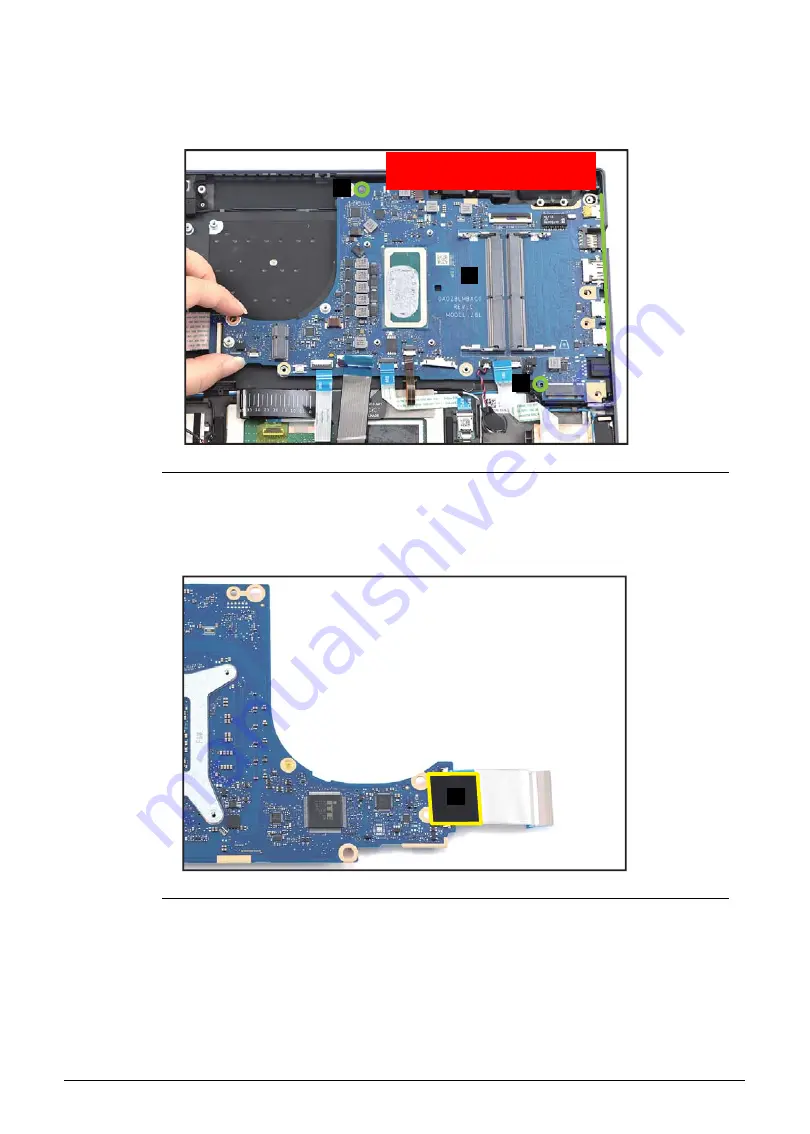
14. Release the mainboard (P) from the I/O connectors slots and guide pins (Q) on the top
assembly (
). Then remove the mainboard.
Figure 1-44. Mainboard Removal
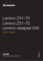
15. Flip the mainboard and detach the tape (R) securing the DB FFC connection
(
).
Figure 1-45. Mainboard Removal
P
Q
WEEE Annex VII Component:
Mainboard
Q
R


