4-6
Troubleshooting
No Display Issues
0
If the Display does not work, perform the following:
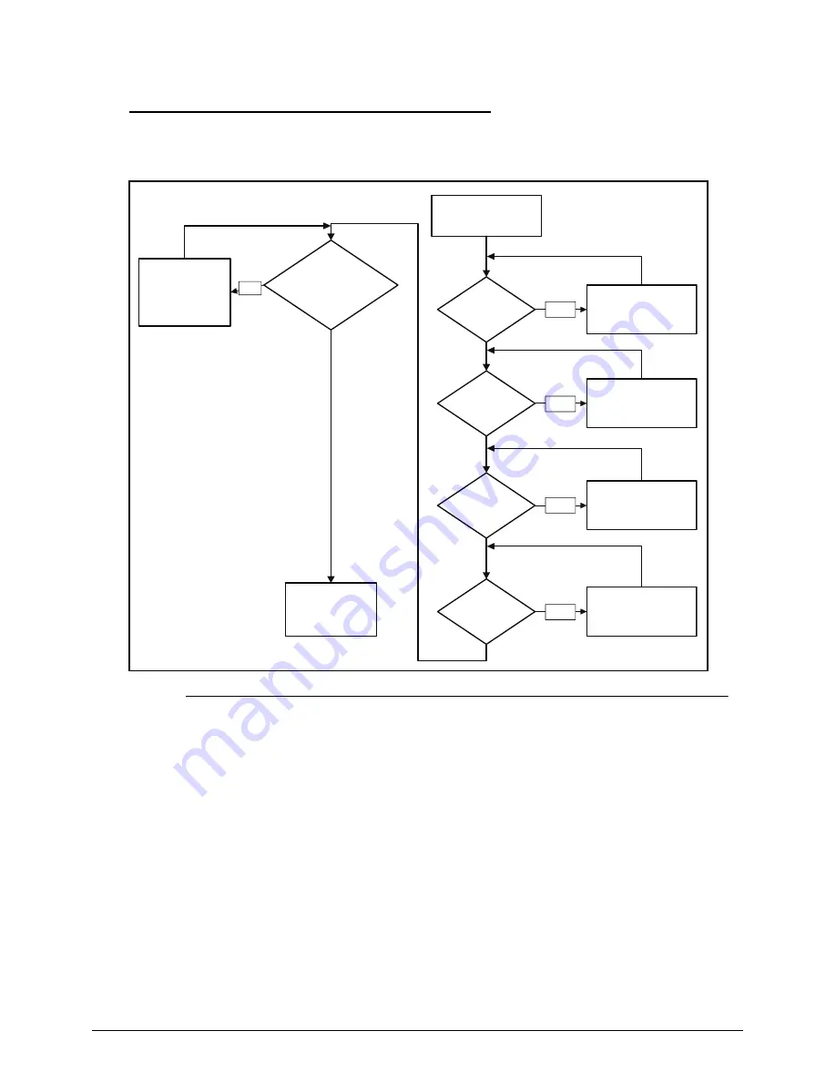
Figure 4-2. No Display Issue
No POST or Video
0
If the POST or video does not appear, perform the following:
1. Make sure that internal display is selected. Switching between internal and external
by pressing
Fn+F5
. Reference product pages for specific model procedures.
2. Make sure the computer has power by checking for one of the following:
Fans start up
Status LEDs illuminate
If no power, refer to
Power On Issues
.
3. Drain stored power by removing the power cable and battery. Hold the power
button for 10 seconds.
4. Connect the power and reboot the computer.
5. Connect an external monitor to the computer and switch between the internal
Go to Power
On Issue
START
Power On?
Ext. DDRRAM
module well
connected?
Ext. DDRRAM
module OK?
CPU thermal
module well
screw?
Replace
M/B
Connect
it well
Replace
Ext. DDR RAM
module
Screw it well
Replace
LCD panel/
LCD cable
LCD module
OK?
No
No
No
No
No
Summary of Contents for TravelMate P243-M
Page 1: ...TravelMate P243 Series SERVICEGUIDE ...
Page 11: ...CHAPTER 1 Hardware Specifications ...
Page 14: ...1 4 ...
Page 67: ...CHAPTER 2 System Utilities ...
Page 96: ...2 30 System Utilities ...
Page 97: ...CHAPTER 3 Machine Maintenance Procedures ...
Page 100: ...3 4 ...
Page 108: ...3 12 Machine Maintenance Procedures ID Size Quantity Screw Type A M2 5 6 0 1 C M2 0 3 0 2 ...
Page 120: ...3 24 Machine Maintenance Procedures ID Size Quantity Screw Type C M2 5 4 1 ...
Page 123: ...Machine Maintenance Procedures 3 27 ID Size Quantity Screw Type C M2 5 4 2 ...
Page 125: ...Machine Maintenance Procedures 3 29 ID Size Quantity Screw Type B M2 2 4 ...
Page 147: ...Machine Maintenance Procedures 3 51 ID Size Quantity Screw Type A M2 5 4 6 ...
Page 163: ...Machine Maintenance Procedures 3 67 ID Size Quantity Screw Type C M2 5 4 1 ...
Page 174: ...3 78 Machine Maintenance Procedures ID Size Quantity Screw Type A M2 5 6 0 1 C M2 0 3 0 2 ...
Page 177: ...CHAPTER 4 Troubleshooting ...
Page 201: ...CHAPTER 5 Jumper and Connector Locations ...
Page 208: ...5 8 Jumper and Connector Locations ...
Page 209: ...CHAPTER 6 FRU Field Replaceable Unit List ...
Page 210: ...6 2 Exploded Diagrams 6 4 FRU List 6 8 Screw List 6 18 ...
Page 227: ...CHAPTER 7 Model Definition and Configuration ...
Page 228: ...7 2 TravelMate P243 Series 7 3 ...
Page 256: ...7 30 Model Definition and Configuration ...
Page 257: ...CHAPTER 8 Test Compatible Components ...
Page 258: ...8 2 Microsoft Windows 7 Environment Test 8 4 ...
Page 269: ...CHAPTER 9 Online Support Information ...
Page 270: ...9 2 Introduction 9 3 ...


