


Chapter 5
227
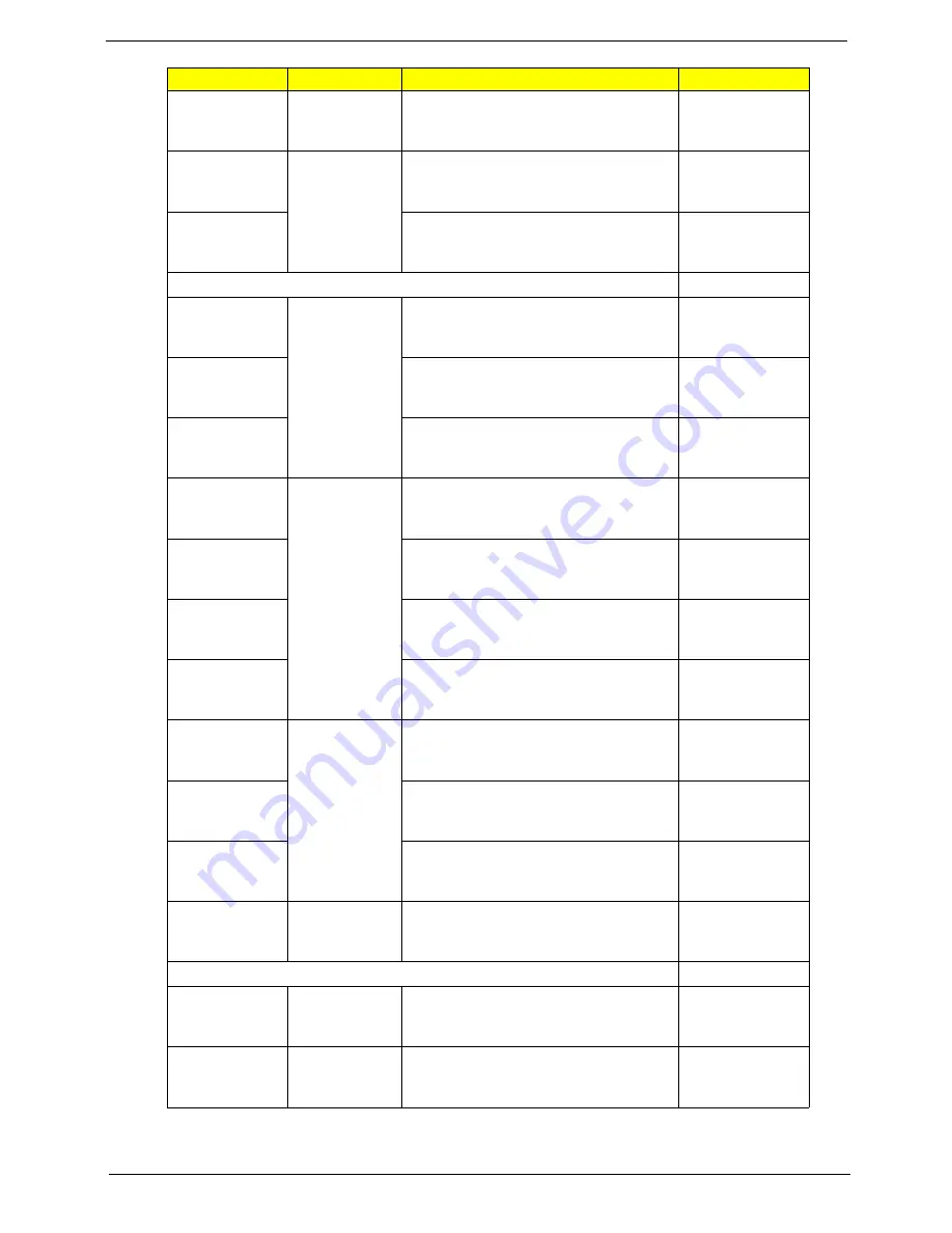
HGST
HDD HGST 2.5" 7200rpm 500GB
HTS725050A9A364 SATA 8MB LF F/W:
C70E
TOSHIBA
640GB/
5400rpm
HDD TOSHIBA 2.5" 5400rpm 640GB
MK6465GSX,Capricorn BS,320G/P
SATA 8MB LF F/W:GJ002J
WD
HDD WD 2.5" 5400rpm 640GB
WD6400BEVT-22A0RT0, ML320 SATA
8MB LF F/W:01.01A01
Battery
Sanyo
3CELL2.2
Battery SANYO UM-2009E Li-Ion 3S1P
SANYO 3 cell 2200mAh Main
COMMON ID : UM09E32
PANASONIC
Battery PANASONIC UM-2009E Li-Ion
3S1P PANASONIC 3 cell 2200mAh
Main COMMON ID: UM09E52
SIMPO
Battery SIMPLO UM-2009E Li-Ion 3S1P
PANASONIC 3 cell 2200mAh Main
COMMON ID:UM09E72
SANYO
6CELL2.2
Battery SANYO UM-2009E Li-Ion 3S2P
SANYO 6 cell 4400mAh Main
COMMON ID: UM09E31
PANASONIC
Battery PANASONIC UM-2009E Li-Ion
3S2P PANASONIC 6 cell 4400mAh
Main COMMON ID:UM09E51
SIMPO
Battery SIMPLO UM-2009E Li-Ion 3S2P
PANASONIC 6 cell 4400mAh Main
COMMON ID:UM09E71
SIMPO
Battery SIMPLO UM-2009E Li-Ion 3S2P
SAMSUNG 6 cell 4400mAh Main
COMMON ID:UM09E75
Sanyo
6CELL2.8
Battery SANYO UM-2009E Li-Ion 3S2P
SANYO 6 cell 5600mAh Main
COMMON ID:UM09E36
SIMPO
Battery SIMPLO UM-2009E Li-Ion 3S2P
SAMSUNG 6 cell 5600mAh Main
COMMON ID:UM09E70
SIMPO
Battery SIMPLO UM-2009E Li-Ion 3S2P
LGC 6 cell 5600mAh Main COMMON
ID:UM09E78
PANASONIC
6CELL2.9
Battery PANASONIC UM-2009E Li-Ion
3S2P PANASONIC 6 cell 5800mAh
Main COMMON ID:UM09E56
Keyboard NT1T_A10B
Darfon
Standard for
Trial Run
Keyboard ACER NT1T_A10B NT1T
Internal 11 Standard Black NONE Y2010
Acer Legend Texture
Darfon
Arabic
Battery PANASONIC UM-2009E Li-Ion
3S1P PANASONIC 3 cell 2200mAh
Main COMMON ID: UM09E52
Vendor
Type
Description
PN
Summary of Contents for TRAVELMATE 8172
Page 6: ...6 ...
Page 49: ...Chapter 2 41 3 Insert the flash disk with the unzip file 4 Connect the adapter ...
Page 52: ...44 Chapter 2 3 Insert the flash disk with the unzip file 4 Connect the adapter ...
Page 57: ...Chapter 2 49 3 Insert the flash disk with the unzip file 4 Connect the adapter ...
Page 61: ...Chapter 2 53 11 Enter the password and the HDD lock will be released ...
Page 63: ...Chapter 2 55 3 Insert the flash disk with the unzip file 4 Connect the adapter ...
Page 66: ...58 Chapter 2 3 Insert the flash disk with the unzip file 4 Connect the adapter ...
Page 67: ...Chapter 2 59 5 Log in dos mode and type dmi174r to execute the program 6 Activate the program ...
Page 68: ...60 Chapter 2 7 Type DMI174 can check all of the function of DMI ...
Page 70: ...62 Chapter 2 3 Insert the flash disk with the unzip file 4 Connect the adapter ...
Page 72: ...64 Chapter 2 7 Go in to the file of MAC Insert the ßmacin bat 8 Input the MAC address ...
Page 74: ...66 Chapter 2 3 Insert the flash disk with the unzip file 4 Connect the adapter ...
Page 76: ...68 Chapter 2 ...
Page 82: ...74 Chapter 3 Removing the HDD 1 Remove two 2 screws on the HDD cover ...
Page 83: ...Chapter 3 75 2 Remove the HDD cover 3 Grasp the pull tab on the top of HDD ...
Page 84: ...76 Chapter 3 4 Lift the HDD out of lower case 5 Remove the HDD connector ...
Page 85: ...Chapter 3 77 6 Remove the HDD bracket 7 Remove the HDD pocket ...
Page 86: ...78 Chapter 3 Removing the DIMM module 1 Remove two screws on the RAM cover ...
Page 87: ...Chapter 3 79 2 Remove the RAM cover Remove the RAM cover 3 Remove the first RAM from RAM slot ...
Page 88: ...80 Chapter 3 4 Remove the second RAM from RAM slot ...
Page 93: ...Chapter 3 85 3 Carefully flip the keyboard over 4 Unlock the keyboard FFC ...
Page 94: ...86 Chapter 3 5 Disconnect the keyboard FFC ...
Page 96: ...88 Chapter 3 3 Unlock the power board FFC 4 Disconnect the power board FFC ...
Page 97: ...Chapter 3 89 5 Remove two screws on the topper case Type Number M2 6 2 ...
Page 100: ...92 Chapter 3 3 Grab the tape on the WLAN cable 4 Remove the tape on the WLAN cable ...
Page 101: ...Chapter 3 93 5 Release WLAN cable 6 Remove 3G tape with the same method ...
Page 102: ...94 Chapter 3 7 Release the 3G cable 8 Grab the CCD connector ...
Page 103: ...Chapter 3 95 9 Disconnect the CCD connector 10 Grab the MIC cable ...
Page 104: ...96 Chapter 3 11 Disconnect the MIC cable 12 Remove the screw from left hinge ...
Page 107: ...Chapter 3 99 3 Remove the Bluetooth module ...
Page 110: ...102 Chapter 3 5 Lift the power bracket from the mainboard 6 Grab the speaker connector ...
Page 112: ...104 Chapter 3 9 Remove the Mainboard from button case ...
Page 113: ...Chapter 3 105 10 Remove speaker module 11 Grab the speaker module and remove it carefully ...
Page 114: ...106 Chapter 3 12 Disassemble the power connection 13 Disassemble fan connector ...
Page 115: ...Chapter 3 107 14 Release four screws on the thermal module 15 Remove thermal module ...
Page 117: ...Chapter 3 109 18 Remove the LED board 19 Release the connector of power board ...
Page 120: ...112 Chapter 3 24 Remove the touch pad board ...
Page 124: ...116 Chapter 3 5 Remove four screws on the corner of LCM Type Number M2 5 4 2 M2 3 1 ...
Page 125: ...Chapter 3 117 6 Lift the panel out ...
Page 126: ...118 Chapter 3 Removing the Camera Board 1 Disconnect the webcam 2 Remove webcam module ...
Page 127: ...Chapter 3 119 Remove the Antennas 1 Release four screws from the LCD bracket ...
Page 129: ...Chapter 3 121 4 Remove the microphone 5 Remove the three tapes on the antenna cable ...
Page 131: ...Chapter 3 123 8 Remove the LAN white antenna 9 Remove the LAN white antenna aluminum foil ...
Page 133: ...Chapter 3 125 3 Replace the LAN black antenna aluminum foil 4 Replace the LAN black antenna ...
Page 134: ...126 Chapter 3 5 Replace the microphone cable 6 Replace the three tapes on the antenna cable ...
Page 135: ...Chapter 3 127 7 Lay the microphone cable in the LCD cover 8 Replace the microphone ...
Page 139: ...Chapter 3 131 3 Replace the panel on the top case ...
Page 143: ...Chapter 3 135 Replacing the Mainboard 1 Assemble the touch pad board 2 Fasten the touch pad ...
Page 145: ...Chapter 3 137 5 Fasten the screw of the power board 6 Install the FFC to the power board ...
Page 146: ...138 Chapter 3 7 Install the LED board 8 Fasten the screw of the LED board ...
Page 147: ...Chapter 3 139 9 Install the FFC on the LED board and stable it 10 Install the thermal module ...
Page 148: ...140 Chapter 3 11 Fasten four screws on the thermal module 12 Replace the fan connector ...
Page 149: ...Chapter 3 141 13 Replace the power connection 14 Insert the speaker module in the slot ...
Page 151: ...Chapter 3 143 17 Fasten four screws on the mainboard 18 Insert the power bracket ...
Page 153: ...Chapter 3 145 2 Fasten two screws on the left and right hinge 3 Replace the CCD connector ...
Page 155: ...Chapter 3 147 6 Replace the LVDS cable 7 Replace the MIC cable ...
Page 157: ...Chapter 3 149 10 Add two tapes on the 3G cable 11 Assemble the speaker connector ...
Page 160: ...152 Chapter 3 Replacing the Upper Case 1 Assemble the upper case ...
Page 161: ...Chapter 3 153 2 Fasten two screws on the upper case ...
Page 163: ...Chapter 3 155 5 Replace the speaker connection 6 Release the lock of the touch pad connection ...
Page 168: ...160 Chapter 3 3 Insert another DIMM with the same method 4 Insert the RAM door ...
Page 169: ...Chapter 3 161 5 Press down the RAM door 6 Fasten two screws on the RAM door ...
Page 170: ...162 Chapter 3 Replacing HDD module 1 Insert HDD connector 2 Insert the HDD into the HDD slot ...
Page 172: ...164 Chapter 3 Replacing the battery 1 Insert the battery carefully 2 Lock the battery lock ...
Page 194: ...186 Chapter 5 ...
Page 210: ...202 Chapter 6 ...
Page 230: ...222 Chapter 5 ...
Page 240: ...232 Appendix C ...