


Chapter 1
5
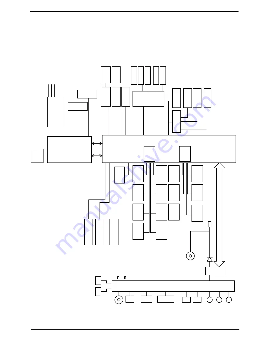
System Block Diagram
DML`HFO
JDT:MST42:8BLMGU
Q/37
244NI{,0. 211NI{,0. 59NI{ 38NI{0:7NI{,0.
y3
y2
y2
y2
TJN!Tmpu
Q/43
Q/44
GBO
Q/27
Q/27.2:
Q/38
Q/38
Q/41
Q/31.36
Q/42
Q/46
Q/46
Q/42
Q/42
Q/42
Q/43
Q/44
Q/47
Q/3:
Q/3:
Q/3:
Q/45
Q/44
IEE
VTC1
VTC2
VTC3
VTC4
VTC5
VTC6
VTC7
VTC8
VTC22
Qpsu2
Qpsu3
GjohfsQsjou
TJN
QNV'LCD
91Qpsu
Bobmph!Pvu
Hmjef!Qbe
LC
JouNjd
Tufsfp
Bobmph!Jo
Bvejp
TQL
HcF
NjojDbse!
Q/43
Q/43
TPEJNN1
TPEJNN2
DQV,HNDI
nCHB!2182qjo
Jcfyqfbl.N
ENJ!y5
IEB!35NI{
MQD!4/4W!44NI{
Pvu
2
$
J
D
I
F
2
/
2
0
1
/
3
!
C
T
V
FIDJ$3
TQJ
Tvqqpsu
T1T4!tubuf
Tvqqpsu
T1T4!tubuf
CHB-2399Q
45ny39nn
38nny36nn
CDN68871
QDJ.Fyqsftt!y2!3/6HI{
QDJ.Fyqsftt!y2!3/6HI{
VNUT
Qpsu$4
QL
u$5
NjojDbse!
XMBO
Dpefd
DY31783
Q/42
JO
UF9613F
Q/39
VTC:
Q/46
Gmbti
SPN
EES4!2/6W
!91102177!NI{
Q/43
Q/44
VTC9
VTC21
JO
Q/42
TQEJG
VTC!3/102/2
Qpsu1
IBMM!TXJUDI
Q/44
SK56
Q/41
Tujdl!Qpjou
Pvu
!BSSBOEBMF
GEJ
EES4!2/6W
!91102177!NI{
MWET
SHC
MDE
DSU
Q/39
Q/39
QDJ.Fyqsftt!y2!3/6HI{
Pvu
Q/43
VTC23
VNUT
VTC24
TBUB!261
VTC!3/102/2
VTC!3/102/2
IN66
DbseSfbefs
Epdljoh
Dbnfsb
Cmvfuppui
Q/43
XMBO
Q/47
VTC
VTC
VTC
IQ
NJD
MJOF!JO
Fbtz!Qpsu
VTC
BEJO
SK56
DSU
EWJ
Qpxfs!po!MFE
DSU!jo!MFE
Fbtz!Qpsu!Dbcmf!Dpo
EPDL`BEQJO
E48
BEJO
M7
Summary of Contents for TRAVELMATE 8172
Page 6: ...6 ...
Page 49: ...Chapter 2 41 3 Insert the flash disk with the unzip file 4 Connect the adapter ...
Page 52: ...44 Chapter 2 3 Insert the flash disk with the unzip file 4 Connect the adapter ...
Page 57: ...Chapter 2 49 3 Insert the flash disk with the unzip file 4 Connect the adapter ...
Page 61: ...Chapter 2 53 11 Enter the password and the HDD lock will be released ...
Page 63: ...Chapter 2 55 3 Insert the flash disk with the unzip file 4 Connect the adapter ...
Page 66: ...58 Chapter 2 3 Insert the flash disk with the unzip file 4 Connect the adapter ...
Page 67: ...Chapter 2 59 5 Log in dos mode and type dmi174r to execute the program 6 Activate the program ...
Page 68: ...60 Chapter 2 7 Type DMI174 can check all of the function of DMI ...
Page 70: ...62 Chapter 2 3 Insert the flash disk with the unzip file 4 Connect the adapter ...
Page 72: ...64 Chapter 2 7 Go in to the file of MAC Insert the ßmacin bat 8 Input the MAC address ...
Page 74: ...66 Chapter 2 3 Insert the flash disk with the unzip file 4 Connect the adapter ...
Page 76: ...68 Chapter 2 ...
Page 82: ...74 Chapter 3 Removing the HDD 1 Remove two 2 screws on the HDD cover ...
Page 83: ...Chapter 3 75 2 Remove the HDD cover 3 Grasp the pull tab on the top of HDD ...
Page 84: ...76 Chapter 3 4 Lift the HDD out of lower case 5 Remove the HDD connector ...
Page 85: ...Chapter 3 77 6 Remove the HDD bracket 7 Remove the HDD pocket ...
Page 86: ...78 Chapter 3 Removing the DIMM module 1 Remove two screws on the RAM cover ...
Page 87: ...Chapter 3 79 2 Remove the RAM cover Remove the RAM cover 3 Remove the first RAM from RAM slot ...
Page 88: ...80 Chapter 3 4 Remove the second RAM from RAM slot ...
Page 93: ...Chapter 3 85 3 Carefully flip the keyboard over 4 Unlock the keyboard FFC ...
Page 94: ...86 Chapter 3 5 Disconnect the keyboard FFC ...
Page 96: ...88 Chapter 3 3 Unlock the power board FFC 4 Disconnect the power board FFC ...
Page 97: ...Chapter 3 89 5 Remove two screws on the topper case Type Number M2 6 2 ...
Page 100: ...92 Chapter 3 3 Grab the tape on the WLAN cable 4 Remove the tape on the WLAN cable ...
Page 101: ...Chapter 3 93 5 Release WLAN cable 6 Remove 3G tape with the same method ...
Page 102: ...94 Chapter 3 7 Release the 3G cable 8 Grab the CCD connector ...
Page 103: ...Chapter 3 95 9 Disconnect the CCD connector 10 Grab the MIC cable ...
Page 104: ...96 Chapter 3 11 Disconnect the MIC cable 12 Remove the screw from left hinge ...
Page 107: ...Chapter 3 99 3 Remove the Bluetooth module ...
Page 110: ...102 Chapter 3 5 Lift the power bracket from the mainboard 6 Grab the speaker connector ...
Page 112: ...104 Chapter 3 9 Remove the Mainboard from button case ...
Page 113: ...Chapter 3 105 10 Remove speaker module 11 Grab the speaker module and remove it carefully ...
Page 114: ...106 Chapter 3 12 Disassemble the power connection 13 Disassemble fan connector ...
Page 115: ...Chapter 3 107 14 Release four screws on the thermal module 15 Remove thermal module ...
Page 117: ...Chapter 3 109 18 Remove the LED board 19 Release the connector of power board ...
Page 120: ...112 Chapter 3 24 Remove the touch pad board ...
Page 124: ...116 Chapter 3 5 Remove four screws on the corner of LCM Type Number M2 5 4 2 M2 3 1 ...
Page 125: ...Chapter 3 117 6 Lift the panel out ...
Page 126: ...118 Chapter 3 Removing the Camera Board 1 Disconnect the webcam 2 Remove webcam module ...
Page 127: ...Chapter 3 119 Remove the Antennas 1 Release four screws from the LCD bracket ...
Page 129: ...Chapter 3 121 4 Remove the microphone 5 Remove the three tapes on the antenna cable ...
Page 131: ...Chapter 3 123 8 Remove the LAN white antenna 9 Remove the LAN white antenna aluminum foil ...
Page 133: ...Chapter 3 125 3 Replace the LAN black antenna aluminum foil 4 Replace the LAN black antenna ...
Page 134: ...126 Chapter 3 5 Replace the microphone cable 6 Replace the three tapes on the antenna cable ...
Page 135: ...Chapter 3 127 7 Lay the microphone cable in the LCD cover 8 Replace the microphone ...
Page 139: ...Chapter 3 131 3 Replace the panel on the top case ...
Page 143: ...Chapter 3 135 Replacing the Mainboard 1 Assemble the touch pad board 2 Fasten the touch pad ...
Page 145: ...Chapter 3 137 5 Fasten the screw of the power board 6 Install the FFC to the power board ...
Page 146: ...138 Chapter 3 7 Install the LED board 8 Fasten the screw of the LED board ...
Page 147: ...Chapter 3 139 9 Install the FFC on the LED board and stable it 10 Install the thermal module ...
Page 148: ...140 Chapter 3 11 Fasten four screws on the thermal module 12 Replace the fan connector ...
Page 149: ...Chapter 3 141 13 Replace the power connection 14 Insert the speaker module in the slot ...
Page 151: ...Chapter 3 143 17 Fasten four screws on the mainboard 18 Insert the power bracket ...
Page 153: ...Chapter 3 145 2 Fasten two screws on the left and right hinge 3 Replace the CCD connector ...
Page 155: ...Chapter 3 147 6 Replace the LVDS cable 7 Replace the MIC cable ...
Page 157: ...Chapter 3 149 10 Add two tapes on the 3G cable 11 Assemble the speaker connector ...
Page 160: ...152 Chapter 3 Replacing the Upper Case 1 Assemble the upper case ...
Page 161: ...Chapter 3 153 2 Fasten two screws on the upper case ...
Page 163: ...Chapter 3 155 5 Replace the speaker connection 6 Release the lock of the touch pad connection ...
Page 168: ...160 Chapter 3 3 Insert another DIMM with the same method 4 Insert the RAM door ...
Page 169: ...Chapter 3 161 5 Press down the RAM door 6 Fasten two screws on the RAM door ...
Page 170: ...162 Chapter 3 Replacing HDD module 1 Insert HDD connector 2 Insert the HDD into the HDD slot ...
Page 172: ...164 Chapter 3 Replacing the battery 1 Insert the battery carefully 2 Lock the battery lock ...
Page 194: ...186 Chapter 5 ...
Page 210: ...202 Chapter 6 ...
Page 230: ...222 Chapter 5 ...
Page 240: ...232 Appendix C ...