


72
Chapter 4
Index of Symptom-to-FRU Error Message
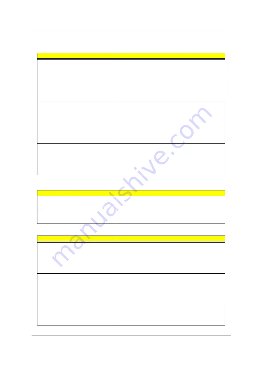
LCD-Related Symptoms
Symptom / Error
Action in Sequence
LCD backlight doesn't work
First, plug a monitor to CRT port. Next, enter BIOS utility to running
“Load Default Settings” then reboot the system.
Reconnect the LCD connectors.
Keyboard (if the brightness function key doesn't work).
LCD cable
LCD inverter
LCD
Main board
LCD is too dark
LCD brightness cannot be adjusted
Enter BIOS Utility to execute “Load Setup Default Settings”, then
reboot system.
Reconnect the LCD connectors.
Keyboard (if the brightness function key doesn't work).
LCD cable
LCD inverter
LCD
Main board
Unreadable LCD screen
Missing pels in characters
Abnormal screen
Wrong color displayed
LCD has extra horizontal or vertical lines
displayed.
Reconnect the LCD cable
LCD cable
LCD
Main board
Indicator-Related Symptoms
Symptom / Error
Action in Sequence
Indicator incorrectly remains off or on, but system
runs correctly
Main board
HDD/CD-ROM active indicators cannot work
HDD/CD-ROM drive
Device driver
Main board
Power-Related Symptoms
Symptom / Error
Action in Sequence
Power shuts down during operation
Power source (battery pack and power adapter). See “Power
System Check” on page 67.
Battery pack
AC adapter
See if the thermal module is overheat (Heat sink or fan).
Main board
The system cannot power-on.
Power source (battery pack and power adapter). See “Power
System Check” on page 67.
Battery pack
Power adapter
CPU
Main board
The system cannot power-off.
In Windows XP operating system, hold and press the power switch
for more than 4 seconds. If the system can power off, then the main
board is OK. Verify OS in the HDD.
Main board
Summary of Contents for TravelMate 540 Series
Page 6: ...VI ...
Page 42: ...34 Chapter 1 ...
Page 56: ...48 Chapter 2 ...
Page 61: ...Chapter 3 53 Removing the Battery Pack 1 Slide the battery latch 2 Then remove the battery ...
Page 70: ...62 Chapter 3 ...
Page 86: ...78 Chapter 4 ...
Page 90: ...82 Chapter 6 Exploded Diagram The System 1 ...
Page 91: ...Chapter 6 83 The System 2 ...
Page 92: ...84 Chapter 6 LCD Module 14 ...
Page 93: ...Chapter 6 85 LCD Module 15 ...
Page 94: ...86 Chapter 6 ODD Module CD ROM DVD ROM ...
Page 95: ...Chapter 6 87 Combo Drive FDD Module ...
Page 107: ...Chapter 6 99 ...
Page 118: ...110 Appendix B ...
Page 120: ...112 Appendix C ...