


Chapter 1
5
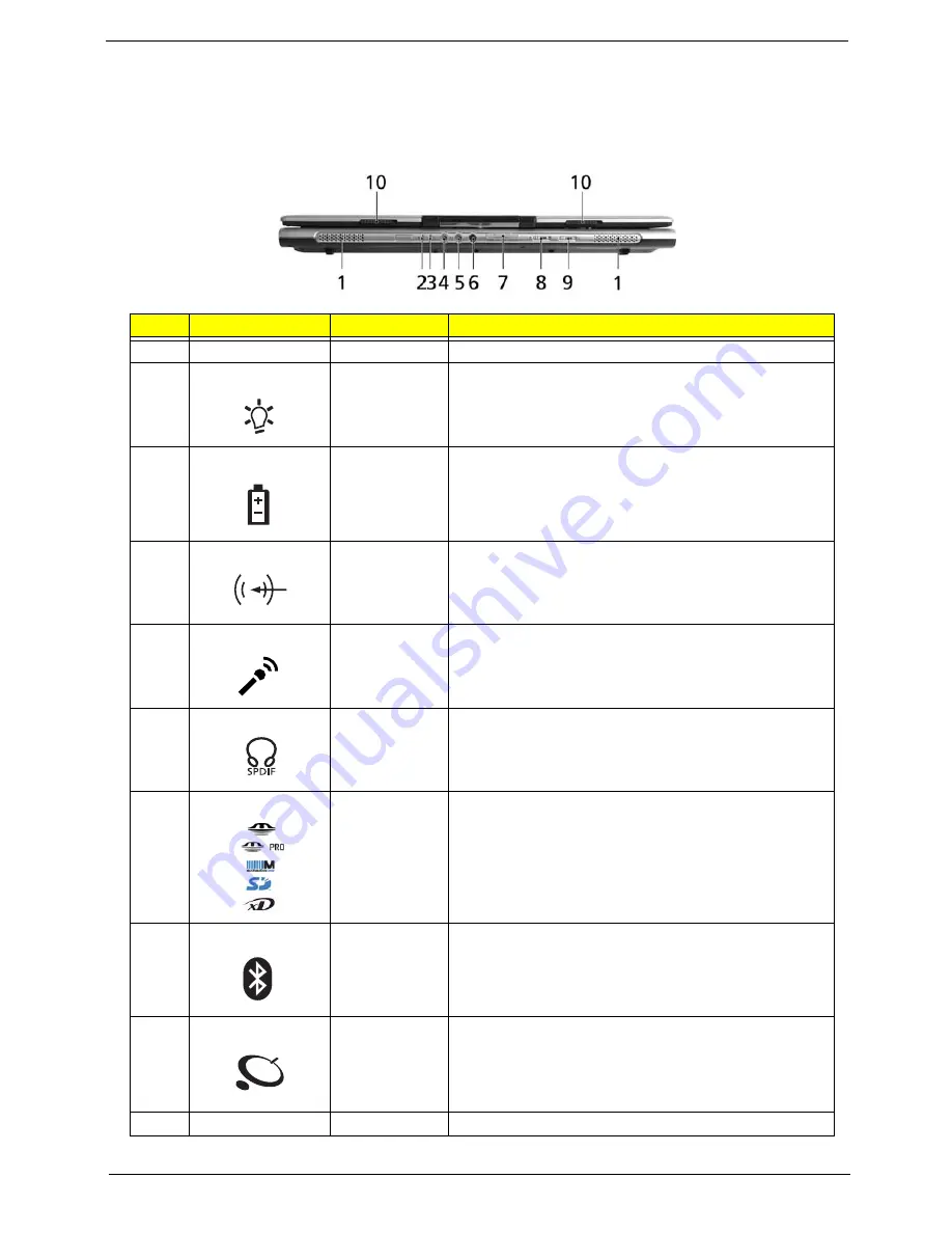
Front View
#
Icon
Item
Description
1
N/A
Speakers
Left and right speakers deliver stereo audio output.
2
Power indicator
Indicates the computer’s power status.
3
Battery indicator Indicates the computer’s battery status.
4
Line-in jack
Accepts audio line-in devices (e.g., audio CD player,
stereo walkman).
5
Mic-in jack
Accepts inputs from external microphones.
6
Headphones/
speaker/line-out
jack with
S/PDIF support
Connects to audio line-out devices(e.g., speakers,
headphones)
7
5-in-1 card
reader
Accepts Memory Stick(MS), Memory Stick PRO(MS
PRO), MultiMediaCard(MMC), Secure Digital (SD) and
xD-Picture Card(xD)
(for TravelMate 4270/4670 Series)
NOTE:
Only one card can operate at any given time.
8
Bluetooth
communication
button/indicator
Press to enable/disable Bluetooth function. Lights to
indicate the status of Bluetooth communications.
9
Wireless
communications
button/indicator
Press to enable/disable Wireless function. Lights to
indicate the status of wireless LAN communications.
(manufacturing option)
10
N/A
Latch
Locks and releases the lid.
"Easy-launch buttons" on page 25
#
Icon
Item
Description
#
Item
Description
"Launch keys" on page 10
#
Icon
Item
Description
#
Item
Description
"Launch keys" on page 10
#
Icon
Item
Description
#
Item
Description
"Launch keys" on page 10
#
Icon
Item
Description
#
Item
Description
"Launch keys" on page 10
#
Icon
Item
Description
#
Item
Description
Note:
#
Icon
Item
Description
#
Icon
Item
Description
Note:
#
Icon
Item
Description
#
Icon
Item
Description
"Launch keys" on page 10
#
Icon
Item
Description
#
Item
Description
"Launch keys" on page 10
#
Icon
Item
Description
#
Item
Description
Summary of Contents for TravelMate 2480
Page 62: ...Chapter 2 56 ...
Page 63: ...57 Chapter 2 ...
Page 70: ...Chapter 3 63 ...
Page 83: ...76 Chapter 3 ...
Page 92: ...Chapter 3 84 3 Place the battery back 4 This completes the main unit reassembly ...
Page 93: ...85 Chapter 3 ...
Page 111: ...102 Chapter 4 ...
Page 112: ...Chapter 5 102 Top View Jumper and Connector Locations Chapter 5 ...
Page 113: ...103 Chapter 5 Bottom View ...
Page 129: ...119 Chapter 6 ...