background image

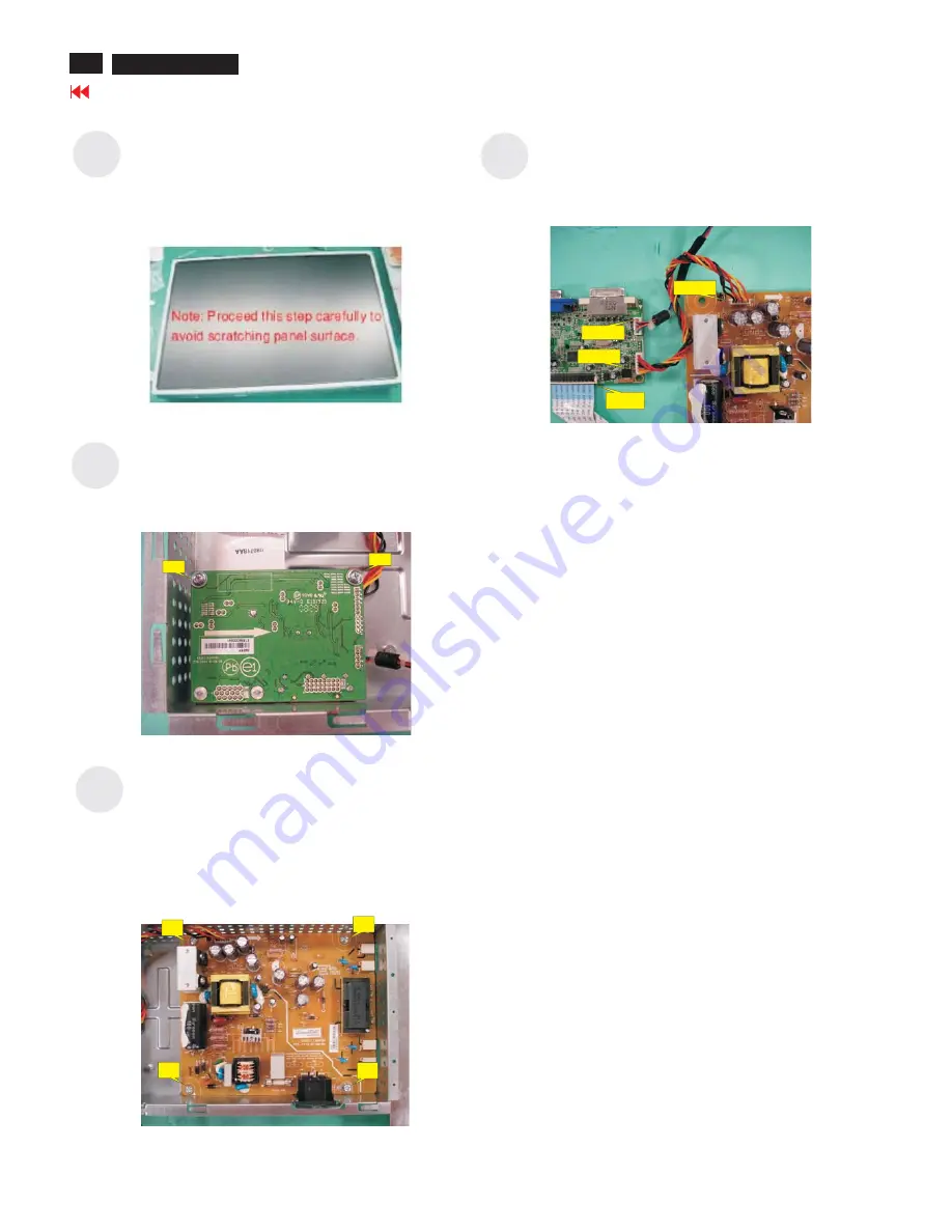
Use a Phillips-head screwdriver unscrewed the

No.1~4 screws to disassemble the power board.

(No 1~3 screw size=M3x6; No 4 screw

size=M4x8; Torque=9~10KGFxCM).

Disconnect all of the cable

Use a Phillips-head screwdriver unscrewed the

No.1~2 screws to release the interface board.

(No1~2 screw size=M3x6; Torque=9~10KGFxCM).

Examine the panel surface accoring to inspection

criteria. Put it aside.

S20

S21

1

2

3

4

1

2

S23

S22

P301

P802

P304

FFC

18

Go to cover page

4. Assembly and Disassembly Procedures (continued)

ACER X193HQ

Summary of Contents for RA19WAANU

Page 1: ...er s Manual 10 Troubleshooting 19 08 Block Diagram 35 04 Assembly and Disassembly Procedures 12 06 Firmware Upgrade Procedure 31 07 Writing EDID Procedure 33 Appendix II Spare Parts List Appendix III Software Pack Service Safety Notice Any person attempting to service this chassis must familarize with the chassis and be aware of the necessary safety precautions to be used when serving electronic e...

Page 2: ...s It is recommended that service engineers should have repairing knowledge experience as well as appropriate product training per new model before performing the service procedures NOTICE To avoid electrical shocks the products should be connect to an authorized power cord and turn off the master power switch each time before removing the AC power cord To prevent the product away from water or exp...

Page 3: ...and transmitting LVDS signals into LCD flat panel module to drive the LCD display circuit The power board will support main power DC5V to interface board and drive the two CCFLs Cold Cathode Fluorescent Tube The interface board provides the power ON OFF control over the whole monitor and control for DPMS LED indicator to function key board Monitor Specifications 1 3 1 Interface Connectors 1 3 1 1 ...

Page 4: ... to G ro u n d N ote 1 S ch m itt T rig g ers Inp u t S u p p orted 3 3 V d ev ice H V sy n c ou tp u t fro m P C V id eo In p u t S ig n a l Pin Signal Pin Signal Pin Signal 1 Red Video 6 Red GND 11 NC 2 Green Video 7 Green GND 12 DDC SDA 3 Blue Video 8 Blue GND 13 H SYNC 4 NC 9 5V 14 V SYNC 5 Connection Detect 10 GND 15 DDC SCL Pin Name Description 1 Red Video Red video signal input 2 Green Vide...

Page 5: ...timings shown in the following page Please see Note 3 1 3 3 4 OSD adjustment 1 Product Specification continued F u n c t i o n L E D C o l o r F u l l P o w e r B l u e c o l o r S l e e p O r a n g e c o l o r T a b l e 1 1 3 3 3 On Screen Display The Lite ON On Screen Display system shall be used controlled by a Menu button If the buttons remain untouched for OSD turn off time while displaying a...

Page 6: ...3 640x480 60Hz 31 469 59 941 25 175 VESA 2 T173 640x480 72Hz 37 861 72 809 31 500 VESA 3 T109 640x480 75Hz 37 500 75 000 31 500 VESA 4 T182 640x480 66 66Hz 35 66 66 30 24 MAC 5 T102 720x400 70Hz 31 469 70 087 28 322 VGA 6 T104 800x600 56Hz 35 156 56 250 36 000 VESA 7 T116 800x600 60Hz 37 879 60 317 40 000 VESA 8 T117 800x600 72Hz 48 077 72 188 50 000 VESA 9 T110 800x600 75Hz 46 875 75 000 49 500 V...

Page 7: ... shall have a continuous operating life of at least 40 000 hours at 25 degree The operating life is defined as having ended when the illumination of light has reached 50 of the initial value The lamps shall extend a sufficient amount from the edge of the light guide that sputtering over the life of the lamps shall not cause degradation of the luminance uniformity such as non illuminated bands alon...

Page 8: ...n g g r a y s h a d e p a t t e r n s B r i g h t S p o t s L i n e s S p o t s o r li n e s t h a t a p p e a r l ig h t i n t h e d is p la y p a t te r n s D e f e c t s d o n o t v a r y i n s iz e o r i n t e n s i ty c o n t r a s t w h e n c o n t r a s t v o l ta g e i s v a r ie d C o n tr a s t v a r ia t io n c a n b e a c h ie v e d th r o u g h th e u s e o f v a r y i n g g r a y s h...

Page 9: ... o s itio n F o c u s a n d C lo c k o f p ic tu re O n ly A n a lo g In p u t M o d e l N A N A N A A n a lo g S e le c t in p u t s ig n a l fro m a n a lo g D S u b O n ly D u a l In p u t M o d e l N A N A N A D ig ita l S e le c t in p u t s ig n a l fro m d ig ita l D V I O n ly D u a l In p u t M o d e l N A N A N A D D C C I s w itc h S e le c t th e D D C C I O N o r O F F N A T h e D D C...

Page 10: ...2 OSD Manu continued 9 Go to cover page ACER X193HQ ...

Page 11: ...3 1 Packing Exploded Diagram 3 Exploded Diagram 10 Go to cover page ACER X193HQ ...

Page 12: ...3 2 Product Exploded Diagram 3 Exploded Diagram continued 11 Go to cover page ACER X193HQ ...

Page 13: ...board P802 and interface board P301 Connect the function key cable into interface board P304 Connect the FFC cable into interface board 4 1 Assembly procedures 4 Assembly and Disassembly Procedures Plug in parallel direction P301 P802 P304 Take the key function cable out from the hole shown as photo Fix the function key cable with a PVC tape 1 2 3 4 1 2 Turn the monitor faced down and put it on th...

Page 14: ...cable Put a ear over n he ssembled nit nd ress on force echanisms ocked nd irmly attached r c o t a u a p m l a f Assemble the stand upper side to the rear cover through the way of screwing 4 screws till both units firmly attached No1 4 Screw Size M4x10 Torque 12 KGFxCM 1 Assemble the hinge cover into both two sides 4 Assembly and Disassembly Procedures continued S11 S10 S6 S8 S7 1 2 3 4 1 2 4 3 1...

Page 15: ... of stand DVI cable and user s manual power cable on specific positions as photo below Move previous assembled parts into the carton then stick Vista and feature label on the carton then packing the carton S18 S16 S15 S14 S17 4 Assembly and Disassembly Procedures continued POWER CABLE DVI CABLE D SUB CABLE USER S MANUAL FEATURE LABEL VISTA LABEL S19 14 Go to cover page ACER X193HQ Stick a screen c...

Page 16: ...he LCD monitor screen faced down Take off two cushion foams Take out all accessories including D SUB cable power cable DVI cables user s manual and packing material from the carton Note It depends on whether users returning the accessories Open the carton with a proper tool S6 S5 S4 S3 S2 S1 S7 4 2 Disassembly procedures 1 2 3 4 FEATURE LABEL VISTA LABEL POWER CABLE DVI CABLE D SUB CABLE USER S MA...

Page 17: ...ar cover separated Separating all of the locking mechanism of the front bezel in turn S8 S13 S12 DOW N SIDE LEFT SIDE RIGHT SIDE UP SIDE S9 S11 S10 Hold the one upside corner of the front bezel after separating the upside of the front bezel Using properly force to pull up front bezel that will let the locking mechanism of left side right side and down side separated 16 Go to cover page 4 Assembly ...

Page 18: ...ection then take out the FFC cable Hold one side of down side that had been separated from front bezel Use properly force to pull up front bezel Take out lamp cables right through the No 1 2 square holes and separate the bracket chassis module and LCD panel apart Unhook the key function board from front bezel disconnect the key function cable S19 S18 S17 S15 S14 S16 1 2 3 4 1 2 17 Go to cover page...

Page 19: ...isconnect all of the cable Use a Phillips head screwdriver unscrewed the No 1 2 screws to release the interface board No1 2 screw size M3x6 Torque 9 10KGFxCM Examine the panel surface accoring to inspection criteria Put it aside S20 S21 1 2 3 4 1 2 S23 S22 P301 P802 P304 FFC 18 Go to cover page 4 Assembly and Disassembly Procedures continued ACER X193HQ ...

Page 20: ...ally OK Proceed checking the resolution change IC movement section NG Input the sync signal of computer or change the cable When a signal isn t being inputted it is indicated with No Signal Input it is indicated with Out Of Range at the time of the frequency that it can t be distinguished 5 1 No display on the screen Screen is black and colour of LED is amber 19 Go to cover page ACER X193HQ ...

Page 21: ... you push the PROCEED key Proceed Abnormal sreen dection OK NG Check the video cable for failure Check the host for output signal is all black or not 1 Change pattern of video signal output on the host 2 Reconnect the video cable 3 Change the video cable NG Check if the LCD video signal cable is connected between the Interface Board and LCD module OK Next Page NG Failure Point The LCD video signal...

Page 22: ...ck the P305 all LVDS signals Failure Point 1 Printed wire broke between P305 and I305 LVDS signals 2 I305 is failure OK NG Failure Point 1 The LVDS cable broke between P305 and LCD module 2 LCD module is failure NG Proceed Checking the DC DC converter circuit section NG Check the I307 pin2 if voltage is 5V Failure Point 1 FB312 is open 2 C353 C355 is short OK Check the I309 pin2 if voltage is 1 8V...

Page 23: ...in 1 at TTL high level OK NG Failure Point 1 printed wire broke between P301 pin1 R303 and I305 pin 88 2 I305 is failure Check the BKLT_ADJ signal of the input P301 pin3 from I305 pin86 is a PWM signal OK NG Failure Point 1 printed wire broke between P301 pin3 R304 R357 and I305 pin11 2 Q302 is failure Failure Point 1 Back light unit of LCD module is failure 2 Inverter Cable disconnect Go to cover...

Page 24: ... 16 respectively that their level is 0 0 to 0 7Vp p Failure Point In the case of the Red signal A Green and Blue signal is the same path too 1 Printed wire broke between P302 pin1 and I305 pin16 2 Video cable is failure 3 FB302 FB306 R327 is open 4 R326 is short or open 5 C315 is short or open NG OK Check all LVDS signals being output to P305 from I305 Failure Point Printed wire broke between I305...

Page 25: ...48 respectively that differential input voltage is 150 to 1200mV and input commond mode voltage is 3 3V Failure Point In the case of the DVI_RX0 signal A DVI_RX1 DVI_RX2 and DVI_RXC signal is the same path too 1 Printed wire broke between P303 pin 17 18 and I305 pin 4 15 2 Video cable is failure 3 R334 R335 open NG OK Check all LVDS signals being output to P305 from I305 Failure Point Printed wire...

Page 26: ...y wire disconnection 2 Function key wire is failure 3 Function key board is failure Check the input TTL level of I305 pin20 21 whether was changed when pressed function keys Refer to Table 1 OK NG Failure Point 1 Printed wire broke among P304 pin3 R350 and I305 pin21 2 Printed wire broke among P304 pin5 R349 and I305 pin20 3 C358 C359 is short 4 R374 R375 is short or open 5 D327 D328 is short Fail...

Page 27: ... failure Check the output signal of serial data clock on I305 pin5 8 OK NG Failure Point I305 is failure Check the voltage on P302 pin9 that is power DC 5 V OK NG Failure Point TheVideo cable is failure Check the signal on P302 pin12 15 that is serial data clock signal OK NG Failure Point The Video cable is failure Failure Point 1 Printed wire broke among I305 pin5 8 R320 R321and P302 pin12 15 2 I...

Page 28: ...oint I305 is failure Check the voltage on P303 pin14 that is power DC 5 V OK NG Failure Point The Video cable is failure Check the voltage on P303 pin 6 7 that is serial data clock signal OK NG Failure Point The Video cable is failure Failure Point 1 Printed wire broke between I305 pin2 3 R344 R345 and P303 pin6 7 2 I305 maybe failure 3 R422 R423 is open or short 4 R344 R345 is open or C337 C336 a...

Page 29: ...7 R319 or C322 is short Failure Point Process Checking the resolution change IC movement section Check the vertical sync signal on P302 pin14 TTL level OK NG Failure Point Video cable is failure Check the horizontal sync signal on I308 pin8 TTL level OK NG Failure Point 1 Printed wire broke between P302 pin14 and I308 pin8 2 FB305 or R308 is open 3 D310 R318 or C313 is short Failure Point Process ...

Page 30: ...nted wire broke between X300 and I305 pin 15 16 2 C340 C341 is short or open 3 X300 failure Check I305 pin 4 RST signal is low level at normal operation OK Check I305 pin 38 39 40 IIC signal OK NG Failure Point 1 Printed wire broke between I305 pin 38 39 40 and I303 pin 5 6 7 2 R351 R352 R353 is open 3 R395 R396 R397 is open or short 4 I303 is failure Failure Point I305 failure Failure Point 1 Pri...

Page 31: ...n2 4 Failure Point I301 is failure or C303 C304 short OK NG Check the 3 3V is input to I309 pin3 OK NG Failure Point 1 Printed wire broke between I302 pin2 4 and I309 pin3 Check the 1 8V is output from I309 pin2 4 Failure Point I309 failure or C368 short OK NG Failure Point 1 Printed wire broke between I301 pin2 4 I309 pin3 2 4 and I308 2 FB309 FB310 is open 5 11 Checking the DC DC converter circu...

Page 32: ...1 for Extend size Connect VGA cable between monitor and kit Connect USB and VGA cable between PC and kit Step 2 Select USB If it shows No USB Device there is a problems with communication you should confirm your USB device whether be detected by your PC device management or reconnect the USB cable again 6 1 Hardware Configuration 31 Go to cover page 6 Firmware Upgrade Process ACER X193HQ ...

Page 33: ..._AAS_F001 EMEA_Extend hex will be loaded in 64 96 automatically Check firmware version Turn off the power then press force on POWER and E button at the same time then press on MENU button to enter factory mode Note Please pay attention Don t change any parameter which is measured by precise machine before shipping out Go to cover page 32 6 Firmware Upgrade Process continued ACER X193HQ ...

Page 34: ...ect the extended DVI cable to DVI socket of monitor Refer to figure 5 6 Re confirm all the connectors are connected well 1 2 3 4 5 6 CAUTION The timing of Chroma shall be setup at T254 P41 before data recording the detail setting parameter from chroma Please See below photo 2 Writing VGA DVI Process Chose the folder or Acer X193H X203H it depends on which model you want to write Select the Acer M1...

Page 35: ...est DDC 5 Key in series number 22 characters in the input column and below empty column Press write button after key in S N 6 When EDID was written successfully that will show below message on the screen Go to cover page 34 7 Writing EDID Process continued ACER X193HQ ...

Page 36: ...eaker Option Function Key Board AC IN Host Computer Audio Source AC to DC Adapter Audio line input Video Signal input DDC Function key input DC 5V Inverter control Panel date control DC power CCFT Drive Speaker line input 1 2 3 4 5 6 7 8 9 10 11 12 13 1 2 3 4 5 6 7 8 9 10 11 12 13 A B C D E F G A B C D E F G Go to cover page 35 ACER X203H ...

Reviews: