


Chapter 6
49
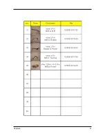
FRU (Field Replaceable Unit) List
This chapter gives you FRU ( Field Replaceable Unit ) listing in global configuration of P
D
-113
P
.
Refer to this chapter whenever ordering for parts to repair or for RMA ( Return Merchandise
Authorization ). Please note that WHEN ORDERING FRU PARTS, you should check the most
up-to-date information available on your regional web or channel. For whatever reasons a part
number change is made, it will not be noted on the printed Service Guide. For Acer AUTHO-
RIZED SERVICE PROVIDERS, Acer office may have a DIFFERENT part number code from
those given in the FRU list of this printed Service Guide. You MUST use the local FRU list pro-
vided by your regional Acer office to order FRU parts for repair and service of customer machines.
NOTE : To scrap or to return the defective parts, you should follow the local government
ordinance or regulations on how to dispose it properly, or follow the rules set by your
regional Acer office on how to return it.
Chapter 6
Summary of Contents for PD-115
Page 12: ...Chapter 1 6 System Block Diagram ...
Page 13: ...7 Chapter 1 Optics Conceptual Drawing ...
Page 21: ...15 Chapter 3 Disassemble Front Fan 1 Lift up the Front f Fan Set from front cover directly ...
Page 32: ...Chapter 3 26 Disassemble DMD Assembly DMD 1 Lift up the DMDAssembly 2 Lift up the DMD ...
Page 41: ...Chapter 4 36 Function Test and Alignment Equipment Needed Test Condition ...
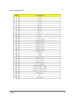
Page 47: ...Chapter 5 42 CN2 Keypad Control ...
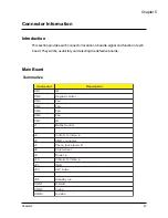
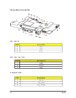
Page 48: ...43 Chapter 5 CON2 Video CON3 S Video J3 J15 Video S Videop IN ...
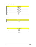
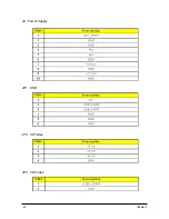
Page 49: ...Chapter 5 44 J7 Phone jack Stereo R CON1 D_SUB J8 Color Wheel ...
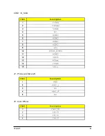
Page 50: ...45 Chapter 5 JP1 USB J9 Power Supply JP3 CW Index JP3 CW Index ...
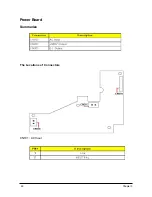
Page 51: ...46 Chapter 5 Power Board Summarize The Locations of Connectors CN101 AC Inout ...
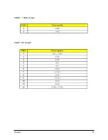
Page 52: ...Chapter 5 47 CN201 380V Output CN301 DC Output ...
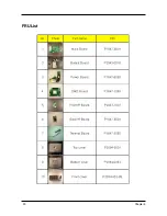
Page 55: ...50 Chapter 6 FRU List ...
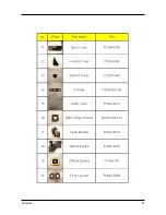
Page 56: ...Chapter 6 51 ...
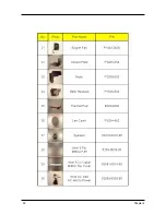
Page 57: ...52 Chapter 6 ...
Page 58: ...Chapter 6 53 ...


