Chapter 4
34
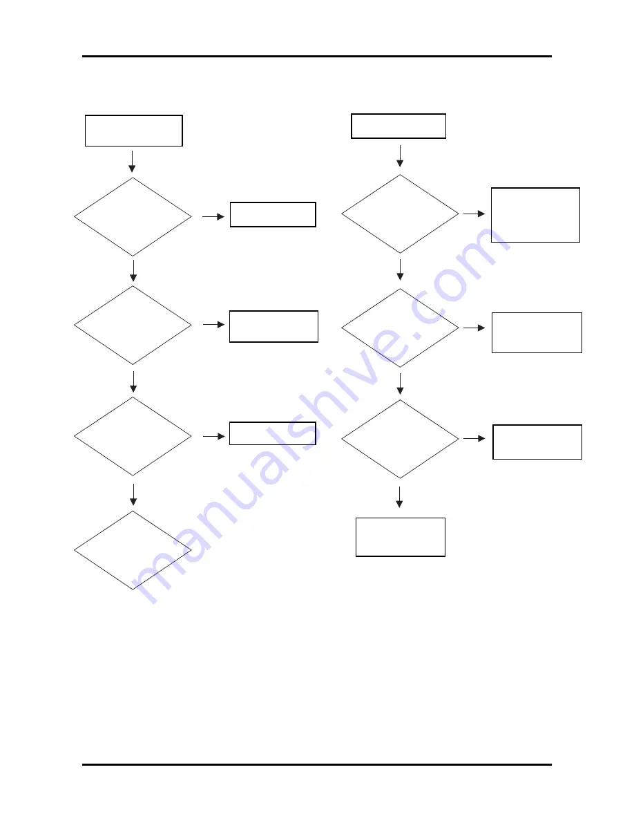
Operation Function:
Remote Control
Failure
Check
Battery
Level
Replace Battery
Check
Remote
Control
Replace Remote
Control
Check
IR
Replace IR
Main
Board Fail
OK
NG
OK
OK
NG
NG
Button Failure
Check
Button
Replace Button
Check
Keypad
Replace Keypad
Replace
Main Board
OK
OK
NG
NG
Check
Top cover’s cable
OK
NG
Replace cable
or connect the
cable back
Summary of Contents for PD-115
Page 12: ...Chapter 1 6 System Block Diagram ...
Page 13: ...7 Chapter 1 Optics Conceptual Drawing ...
Page 21: ...15 Chapter 3 Disassemble Front Fan 1 Lift up the Front f Fan Set from front cover directly ...
Page 32: ...Chapter 3 26 Disassemble DMD Assembly DMD 1 Lift up the DMDAssembly 2 Lift up the DMD ...
Page 41: ...Chapter 4 36 Function Test and Alignment Equipment Needed Test Condition ...
Page 47: ...Chapter 5 42 CN2 Keypad Control ...
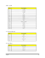
Page 48: ...43 Chapter 5 CON2 Video CON3 S Video J3 J15 Video S Videop IN ...
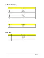
Page 49: ...Chapter 5 44 J7 Phone jack Stereo R CON1 D_SUB J8 Color Wheel ...
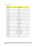
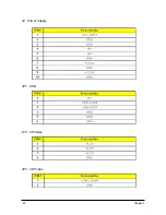
Page 50: ...45 Chapter 5 JP1 USB J9 Power Supply JP3 CW Index JP3 CW Index ...
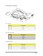
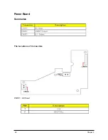
Page 51: ...46 Chapter 5 Power Board Summarize The Locations of Connectors CN101 AC Inout ...
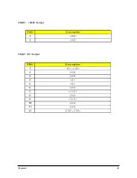
Page 52: ...Chapter 5 47 CN201 380V Output CN301 DC Output ...
Page 55: ...50 Chapter 6 FRU List ...
Page 56: ...Chapter 6 51 ...
Page 57: ...52 Chapter 6 ...
Page 58: ...Chapter 6 53 ...


