background image

6

4.0  Use of the Instrument

4.1 Preparation and Safety Measures
Before connecting the test leads always set the measurement
range switch to the desired function.
Before switching to a new function or to a different measurement
range disconnect the leads from the test object.
The instrument may only be used in dry and clean environments.
Dirt and humidity reduce the insulation resistance and can lead to
electric blows when working with high voltages particularly.
The instrument may only be used within the operating ranges as
specified in the technical data section.
Prior to usage check the instrument for perfect functioning on a
known voltage source (see also DIN VDE 0105, Part 1).

PASAR 323 has an Auto Range function that will automaticly
search for the best measurement range.

4.2  Voltage Measurement AC/DC
Do not connect the probes to more than 600V AC/DC. Exceeding
these values can endanger the operator, and may result in damage
to the instrument.
1)

Select measurement range (V- / V~) via measurement

functionselection switch (4).

2)

Connect the black test lead to the COM socket and the red test

lead to the ”V 

Ω 

mA


” socket.

3)

Connect test leads to UUT.

4)

The value measured is shown on the digital display.

4.3 Current Measurement 10A/15A AC/DC
Do not carry out current measurements in systems with more than
250V.
1)

Select measurement range ”AAC” or ”ADC” via measurement

function selection switch (4).

2)

Connect the black test lead to the COM socket and the red test

lead to the ”15A” socket

3)

Connect multimeter in series to the test object and then switch

on UUT.

Summary of Contents for PASAR 323

Page 1: ...ACER AB Box 261 SE 433 25 PARTILLE Sweden Telefon 46 0 31 446500 Telefax 46 0 31 444410 www acer se Instruction Manual CAT III 600V Digital Multimeter PASAR 323 Copyright 2005 Acer AB All rights reserved ...

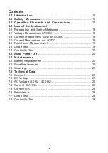
Page 2: ...ent 10A 15A AC DC 18 4 4 Current Measurment mA AC DC 19 4 5 Resistance Measurement 19 4 6 Diode Test 19 4 7 Continuity Test 20 5 0 Auto Power Off 20 6 0 Maintenance 6 1 Battery Replacement 20 6 2 Fuse Replacement 21 6 3 Cleaning 21 7 0 Technical Data 7 1 General 22 7 2 DC Voltage 22 7 3 AC Voltage 50 Hz 400 Hz 22 7 4 Current 10A 15A 22 7 5 Current mA 23 7 6 Resistance 23 7 7 Diode Test 23 7 8 Cont...

Page 3: ... EMV Directive 89 336 EEC Standards EN 50081 1 and EN 50082 1 are fulfilled It also complies with the Low Voltage Directive 73 23 EEC Standard EN 61010 1 is fulfilled After unpacking verify that the instrument is undamaged The scope of supply comprises 1 PASAR 323 2 test leads 2 batteries 1 5V IEC LR03 1 Instruction manual 2 0 Safety Measures PASAR 323 has been constructed and verified in complian...

Page 4: ... instrument are in perfect condition The instrument may only be used under the conditions and for the purposes for which it was constructed For this reason in particular the safety references the technical data including environmental conditions and the usage in dry environments must be followed The opening of the instrument may only be carried out by professionals except for fuse or battery repla...

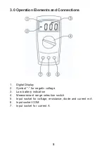
Page 5: ...d Connections 1 Digital Display 2 Symbol for negativ voltage 3 Low battery indication 4 Measurement range selection switch 5 Input socket for voltage resistance diode and current mA 6 Input socket COM 7 Input socket for current A ...

Page 6: ...5 Part 1 PASAR 323 has an Auto Range function that will automaticly search for the best measurement range 4 2 Voltage Measurement AC DC Do not connect the probes to more than 600V AC DC Exceeding these values can endanger the operator and may result in damage to the instrument 1 Select measurement range V V via measurement functionselection switch 4 2 Connect the black test lead to the COM socket ...

Page 7: ...easurment value is 400mA an acoustic signal is audible 4 5 Resistance Measurement Prior to any resistance measurement it has to be ensured that the resistor to be tested is not live Failure to comply with this prescription can lead to dangerous corporal user injuries or cause instrument damage 1 Select measurement range Ω via measurement function selection switch 4 2 Connect the black test lead to...

Page 8: ...C LR03 respect polarity 4 Read the voltage drop in the forward direction from the digital display In the reverese direction OL should appear at the left side of the display Remark The polarity of the test voltage is at the red test lead 4 7 Continuity test 1 Select measurement range via measurement function selection switch 4 2 Connect the black test lead to the COM socket and the red test lead to...

Page 9: ...values in compliance with the technical data section Only use fuses 200mA fast acting 250V 5 x 20mm 10A fast acting 250V 5 x 20 mm 1 Prior to fuse replacement disconnect the instrument from any circuit 2 Switch off instrument 3 Loosen the screws on the instrument rear Lift the case cover 4 Remove the defect fuse and insert as new fuse of the same type Using auxiliary fuses in particular short circ...

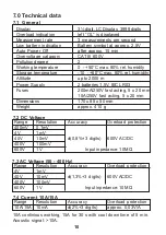
Page 10: ...IEC LR03 Fuses 200mA 250V fast acting 5 x 20 mm 10A 250V fast acting 5 x 20 mm Dimensions 170 x 85 x 50 mm Weight approx 410 g 7 1 General 10A continious working 15A for 30 s with cool down time of 5 min Acoustic signal 10A 7 4 Current 10A 15A Range Resolution Accuracy Overload protection 10A 15A 10mA 2 3 digits approx 0 03V A 7 3 AC Voltage 50 400 Hz Range Resolution Accuracy Overload protection ...

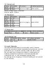
Page 11: ...dropping or incorrect handling are not covered by the warranty 7 5 Current mA Range Resolution Accuracy Overload protection 40mA 10µA 1 5 3 digits 250V AC DC 400mA 100µA Burden voltage approx 10mV mA Acoustic signal 400mA 7 6 Resistance Range Resolution Accuracy Overload protection 400 Ω 0 1 Ω 4 kΩ 1 Ω 40 kΩ 10 Ω 1 5 3 digits 600V AC DC 400 kΩ 100 Ω 4 MΩ 1 kΩ 40 MΩ 10 kΩ 7 8 Continuity test Range ...

Page 12: ...12 ACERAB Box 261 SE 433 25 PARTILLE Sweden Location Brodalsvägen 7 Telefon 46 0 31 44 65 00 Telefax 46 0 31 44 44 10 www acer se ...

Reviews: