background image

Acer  


Acer –LCD-S243HL   


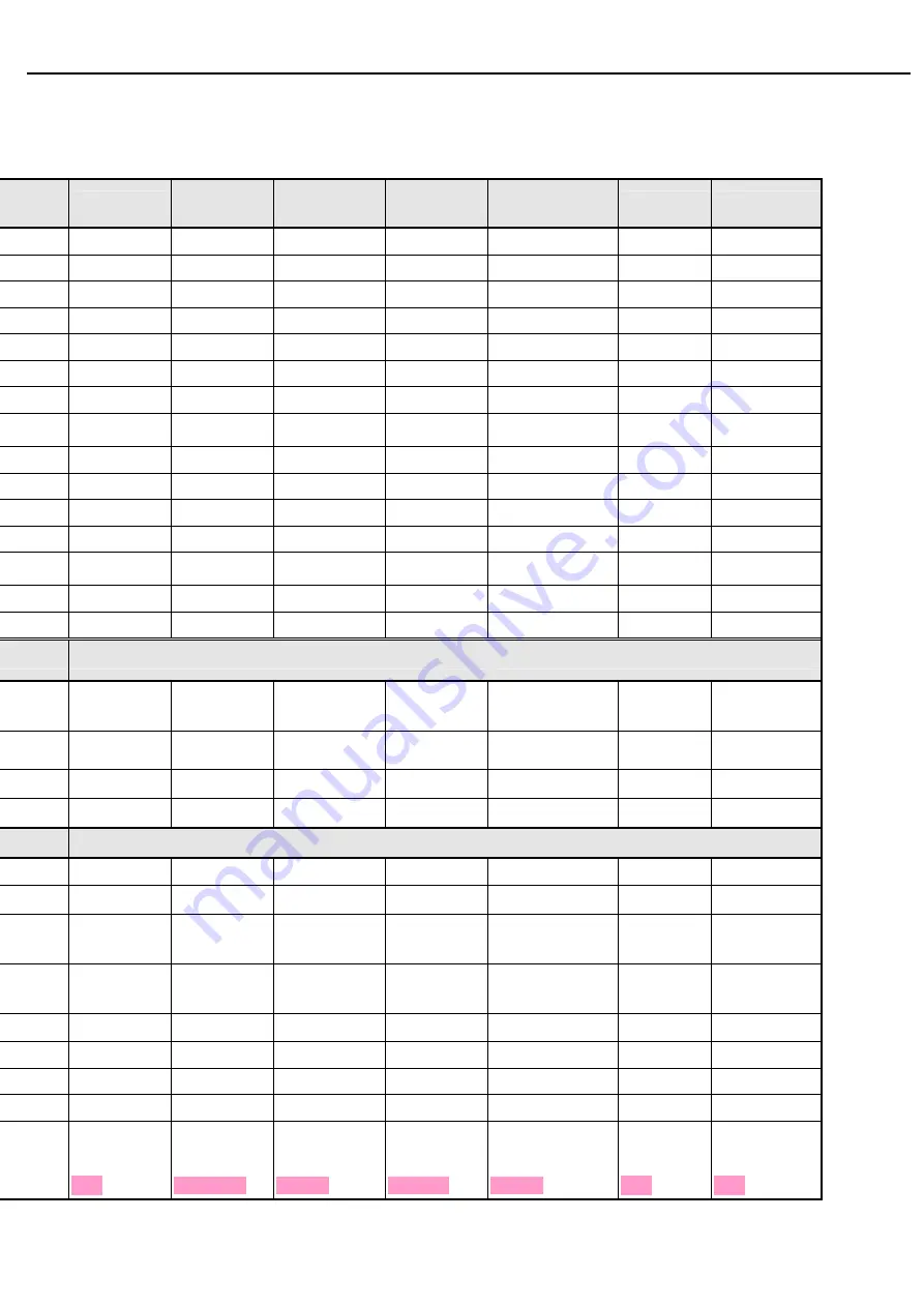
5.5 OSD Translation 

Main menu (NO_EMEA) 

nglish 

繁體中文


Deutsch 

(

Français 

(

Español 

(

西班牙

)

Italiano 

(

意大

利语

体中文


日本語


畫面


Bild Image Imagen 

Immagine 

画面


ピクチャー


ness 

亮度


Helligkeit Luminosité Brillo 

Luminosità 


ast 

對比


Kontrast Contraste Contraste Contrasto 


コントラスト

sition 

水平位置


H.Position H.Position  H.Posicion O.Posizione 

水平位置


水平位置


sition 

垂直位置


V.Position V.Position  V.Posicion V.Posizione 

垂直位置


垂直位置


相位


Fokus Netteté Nitidez Nitidezza 

相位


フェーズ


時脈


Takt Fréquence 

Reloj Orologio 


クロック


r Temp 

色溫


Farbtemp. Temp. 

Couleur 

Temp. Color  Temp. Colore 


色溫度


暖色溫


Warm Chaud  Càlido Caldo 

暖色温


暖色


色溫


Kalt Clair  Frio Freddo 

色温


寒色


使用者設定


Anwender Utilisateur  Usuario  Utente 

使用者设定


ユーザー設定

紅色


Rot Rouge 

Rojo Rossa 


Grün Vert  Verde Verde 

绿


Blau Bleu  Azul Blu 


Config 

自動調整


Autom. Abgl.  Autoréglage 

Autoajuste 

Autoregolazione 

自动


自動調整


OSD 

Timeout 

OSD

顯示時間

設定


OSD-Dauer  Délai de l'OSD 

T. de espera 
OSD 

Intervallo OSD 

OSD

间设定


OSD

表示時間

設定


設定


Einstellung Réglages 

Configuración Impostazione 

设置


設定


Mode 

寬螢幕模式


Vollbild 

Plein écran 

Completa 

Schermo intero 

屏模式


ワイドモード

全螢幕


Vollbild Plein 

écran 

Completa 

Pieno 

全屏


全画面


ct 

Aspect 

輸入


Eingang Entrée 

Entrada  Input 

输入


uage 

語言


Sprache Langue  Idioma  Lingua 


言語


出廠模式

  Rücksetzen Restaurer 

Reiniciar 

Resetare 

恢复出厂模


リセット


e Wait 

請稍待


Bitte warten 

Veuillez 
patienter 

Espere, por 
favor 

Attendere prego 

稍待


お待ちくださ


mation 

資訊


Info Informations 

Información 

Informazioni 

信息


情報


結束調整


Beenden Quitter 

Salida 

Uscita 

退出菜


進入


Eingabe Entrez 

Introducir Invio 


移動


Beweg. Dépla.  Mover  Muovi 

移动


移動


EIN Allumé 

ACTIVADO 

ATTIVA 


オン


Aus OffEteinte 

Apagado 

Spento 

关闭


オフ


me 

音量


Lautstärke 

Volume 

Volumen 

Volume 

音量


音量


  Message menu: (NON_EMEA) 

Summary of Contents for LCD-S243HL

Page 1: ...Acer Acer LCD S243HL Service Manual LCD Monitor Acer S243HL ...

Page 2: ...2 06 Schematics and Layouts 43 07 Assembly and Disassembly 46 Appendix User s manual Copyright Copyright 2009 InnoLux Tech Corp Ltd All Rights Reserved This manual may not in whole or in part be copied Photocopied reproduced translated or converted to any electronic or machine readable form without prior written permission of InnoLux Tech Corp Ltd Acer S243HL Service Manual ...

Page 3: ...lug the power cable immediately and consult your closed dealer z Always unplug the monitor before cleaning it Clean the cabinet with a clean dry cloth Apply non ammonia based cleaner onto the cloth not directly onto the class screen z Do not place heavy objects on the monitor or power cord 2 Product safety notice Many electrical and mechanical parts in this chassis have special safety visual inspe...

Page 4: ...rough OSD control It support HDCP Color management and ACM function 1 1 Main Features Features Specifications Maximum resolution 1920 x3 x 1080 60Hz Back light system 2 LED lightbar top bottom edge side Pixel pitch 276 75 um per one triad x 276 75 um V Display area 531 36mm H x 298 89mm V Contrast ratio 8 000 000 1 ACM ON Brightness 250cd m TYP Response time Tr Tf 2ms GTG Viewing angle 170 H 160 V...

Page 5: ...ntal conditions Operating Specification Low Temperature 0 C Relative Humidity is as low as possible 12 hrs High Temperature 40 C 20 R H 12 hrs High Humidity 32 C 80 R H 12 hrs Altitude 12 000 feet at 25 C hold 3 5 hrs Storage Low Temperature 30 C humidity not controlled High temperature low humidity 65 C 10 R H Test Profile 25 C 50 R H 2hrs 30 C No R H 12hrs 41 C 90 R H 12hrs 65 C 10 R H 12 Hrs 25...

Page 6: ...ws XP Windows Vista Compatibility Energy Star 5 0 Power Management 2 3 Electrostatic Discharge Requirements 2 4 Reliability Items Condition Spec Note MTBF Operating condition is 25 C 60 000 Hours Except panel LED Life time Luminance becomes 50 15 000 Hours TYP Note1 Note1 Operating with fixed driving current Item Condition Spec Contact discharge 4KV Contact discharge 8KV Air discharge 8KV Electros...

Page 7: ...05V 19 95V DC output loading capability 2 1A max Output Ripple and Noise With dummy load 350mV Rise Time 40mS With system 10mS Hold up time With dummy load 6mS Overshoot 10 Turn on delay time 2S Efficiency 80 Power management See Table 1 Note1 Before each test the buck capacitor needs to be discharged Before each test it must be 10 minutes at least after the latest test Hot star not component be d...

Page 8: ...easured band width with DC 20MHz Table 1 Status H sync V sync Video Power LED Power On on on active 32W Blue off on blanked 1W Amber on off blanked 1W Amber Power Saving off off blanked 1W Amber Power Off 1W Off 3 2 Backlight Power Supply Items Specification Panel M240HW01 V6 2 8Bar LED Input Voltage 18 20V Input current 1 2A Typ 1 5A Max On Off switch level 3 6V V on 2 0 V on 0 3v V off 0 8 V off...

Page 9: ...20 x 1080 Video input level 700 mV 2 Warm up time 30 minutes Set brightness control and also contrast control at maximum to measure the screen center the light output shall BL 200 cd m2 3 4 White balance The test standard conditions refer to Sec 3 3 Brightness and contrast are under default value Chromaticity Coordinate Mode x y Cool 9300K 0 283 0 030 0 297 0 030 Warm 6500K 0 313 0 030 0 329 0 030...

Page 10: ...Frequency response range 200Hz 20kHz 4 2HDMI x2 HDMI type A Connector Pin assignment 19 18 17 16 15 14 13 12 10 9 8 7 6 5 4 3 2 1 11 19 18 17 16 15 14 13 12 10 9 8 7 6 5 4 3 2 1 11 Pin Symbol Pin Symbol 1 TMDS Data2 11 Cable detect 2 TMDS Data2 shield 12 TMDS Clock 3 TMDS Data2 13 CEC 4 TMDS Data1 14 N C 5 TMDS Data1 shield 15 SCL 6 TMDS Data1 16 SDA 7 TMDS Data0 17 DDC CEC Ground 8 TMDS Data0 shi...

Page 11: ... in 4 3 1 D sub Connector Pin assignment Pin Symbol 1 Red Video 2 Green Video 3 Blue Video 4 N C 5 Cable detect 6 Red Ground 7 Green Ground 8 Blue Ground 9 PC 3 3 5V 10 Sync Ground 11 N C 12 DDC SDA 13 H sync 14 V sync 15 DDC SCL ...

Page 12: ...79 60 317 40 000 23H SVGA 800x600 72Hz 1040 x 666 48 077 72 188 50 000 N A 1024x600 60Hz 1312x622 37 320 60 000 48 964 N A 1024x768 60Hz 1344x806 48 363 60 004 65 000 24H XGA 1024x768 70Hz 1328x806 56 476 70 069 75 000 24H 1152x864 75Hz 1600x900 67 5 75 108 26H 27H VESA 1280x960 60Hz 1800x1000 60 60 108 N A SXGA 1280x1024 60Hz 1688x1066 63 981 60 020 108 000 25H VESA 1280x720 60Hz 1650x750 44 955 ...

Page 13: ...80i 16 9 720 x 480 13 50 15 73 60 NTSC 480p 4 3 720 x 480 27 00 31 47 60 NTSC 480p 16 9 720 x 480 27 00 31 47 60 PAL 576i 720 x 576 13 50 15 63 50 PAL 576p 4 3 720 x 576 27 00 31 27 50 PAL 576p 16 9 720 x 576 27 00 31 27 50 720p 1280 x 720 74 25 37 5 50 720p 1280 x 720 74 25 44 96 60 1080i 1920 x 1080 74 25 28 125 50 1080i 1920 x 1080 74 25 33 72 60 1080P 1920 x 1080 148 50 56 250 50 1080P 1920 x ...

Page 14: ...1KHz 1Vrms Total harmonic distortion plus noise 10 Po 2 0W Signal to noise ratio dB 40 THD N 5 PWM frequency KHz 200 250 300 Note The low pass RC Filter R 100Ω C 0 047uF for Class D Output Power and THD N Measurement 4 7 DDC data EDID File Format VESA s EDID Standard Version 3 Revision 0 EDID Structure Version 1 Revision 3 EDID Data Table See the attached table for example ...

Page 15: ...18 71 38 2D 40 58 2C 4 45 00 13 2B 21 00 00 1A 00 00 00 FC 00 53 32 34 5 33 48 4C 0A 20 20 20 20 20 20 00 00 00 FD 00 37 6 4B 1E 50 12 00 0A 20 20 20 20 20 20 00 00 00 FF 7 00 30 30 30 30 30 30 30 30 30 30 30 30 0A 01 4A 0 02 03 22 F2 23 09 7F 07 4E 01 02 03 84 05 06 07 1 10 11 12 15 93 1F 14 83 01 00 00 66 03 0C 00 10 2 00 00 8C 0A D0 8A 20 E0 2D 10 10 3E 96 00 13 2A 3 21 00 00 18 01 1D 00 72 51 ...

Page 16: ...lay Colors 16 7M colors RGB 6 bit Hi_FRC Number of Pixel 1920 H 1080 V Full HD Brightness 250 cd m2 TYP Contrast Ratio 1000 TYP Viewing Angle 170 Horizontal 160 Vertical CR 10 Display Mode Normally White Response Time 5ms TYP ON OFF Surface Treatment Anti Glare 3H Lamp 2 LED lightbars Outline Dimension 556 0 W 323 2 H 9 90 D Notice Other second panel please refer to panel spec ...

Page 17: ...buttons POWER Power on or power off the monitor A When Main OSD displays press these keys to change the contents of an adjustment item or change an adjustment value B When Main OSD un displays press to show Audio OSD and increase the volume press to show Audio OSD and decrease the volume MENU A When Main OSD un displays press MENU to enter OSD interface B When Main OSD displays press MENU to perfo...

Page 18: ...Acer Acer LCD S243HL FACTORY MODE ON Press e and then press POWER for DC power on OSD menu will be shown with F on the left top Select F for entering factory mode ...

Page 19: ...mpowering Technology Movie Standard User mode 77 Text mode 44 Standard mode 77 Graphics mode 97 Brightness 0 100 Movie mode 77 User mode 50 Text mode 50 Standard mode 50 Graphics mode 60 Contrast 0 100 Movie mode 56 H Position 0 100 50 V Position 0 100 50 Focus 0 100 Clock 0 100 50 1 Warm Default color temp Cool Red 0 100 80 Green 0 100 80 Color Temp User Blue 0 100 80 Picture Auto Configure H Pos...

Page 20: ...eutsch Deutsch Français Français Español Español Italiano Italiano Dutch 简体中文 Language Finnish 日本語 English Reset Resolution H Freq V Freq Input Type Info S N 2 Volume 0 100 50 Notes 1 Clock default 50 is for Visa timing Others depend on timing 2 Depend on timing S N ...

Page 21: ...erde 绿色 緑 藍色 Blau Bleu Azul Blu 蓝色 青 Config 自動調整 Autom Abgl Autoréglage Autoajuste Autoregolazione 自动调整 自動調整 OSD Timeout OSD 顯示時間 設定 OSD Dauer Délai de l OSD T de espera OSD Intervallo OSD OSD 显示时 间设定 OSD 表示時間 設定 g 設定 Einstellung Réglages Configuración Impostazione 设置 設定 Mode 寬螢幕模式 Vollbild Plein écran Completa Schermo intero 宽屏模式 ワイドモード 全螢幕 Vollbild Plein écran Completa Pieno 全屏 全画面 ct Aspect 輸入 ...

Page 22: ... Utilisateur Usuario Utente 用户 ユーザー t Exit 調整 結束 Abstimmen Bee nden Ajuster Quitter Ajuste salir Regola Esci 调节 退出 調整 終了 t 選擇 Auswahl Sélectionner Seleccionar Seleziona 选取 選択 Main menu EMEA nglish 英语 Russian 俄语 Deutsch 德语 Français 法语 Español 西班牙语 Italiano 意大利语 Dutch 荷兰语 Finnish 芬兰语 e Изображ Bild Image Imagen Immagine Beeld Kuva ness Яркость Helligkeit Luminosité Brillo Luminosità Helderheid Kirkk...

Page 23: ...er Muovi Verpl Liiku Вкл EIN Allumé ACTIVADO ATTIVA AAN PÄÄLLÄ ON Выкл Aus OffEteinte Apagado Spento Uit Pois päältä me Громкость Lautstärke Volume Volumen Volume Volume Äänenvoim Message menu EMEA nglish 英语 Russian 俄语 Deutsch 德语 Français 法语 Español 西班牙语 Italiano 意大利语 Dutch 荷兰语 Finnish 芬兰语 Config e Wait Автонастро йка подождите Autom Abgl Bitte warten Autoréglage Veuillez patienter Autoajuste Espe...

Page 24: ...Mechanical 6 1 Dimension Dimension Spec Width 569mm Height 425mm W Base O BASE Depth 192mm W Base 122mm W O Base Monitor Weight 4 2 0 3Kg for AUO panel AUO panel 2 2Kg Remark If phase in other second panel the Monitor weight 2 0Kg second panel weight 0 3Kg 6 2Cabinet Material Cabinet Material Spec Cabinet Plastic Material ABS HB Front Bezel BLACK Back Cover BLACK Base SILVER Cabinet Texture ACER S...

Page 25: ... panel the Gross weight 4 1Kg second panel weight 0 3Kg 7 1 2 Unit Packing Vibration Testing with vibration shall be done in each of three mutually perpendicular axes Axes are referenced to the position of system as it normally sits in front of user i e Front to back side to side and top to bottom 7 1 2 1 Random Vibration Items Description Sweep Frequency 1 200Hz Amplitude 1 14 Grms Duration Time ...

Page 26: ...ackage Corner Step 2 Edge 3 5 of package Edge Step 3 Edge 2 3 of package Edge Step 4 Edge 2 5 of package Edge Step 5 Face bottom 3 of package Flat Step 6 Face left 4 of package Flat Step 7 Face front 5 of package Flat Step 8 Face right 2 of package Flat Step 9 Face rear 6 of package Flat Step 10 Face Top 1 of package Flat Mechanical and electrical damage should not exist after vibration test and s...

Page 27: ......

Page 28: ...Acer Acer LCD S243HL 02 Flat Panel Specification ...

Page 29: ...Acer Acer LCD S243HL ...

Page 30: ...Acer Acer LCD S243HL ...

Page 31: ...Acer Acer LCD S243HL ...

Page 32: ...Acer Acer LCD S243HL ...

Page 33: ...Acer Acer LCD S243HL ...

Page 34: ...Acer Acer LCD S243HL ...

Page 35: ...Acer Acer LCD S243HL ...

Page 36: ...Acer Acer LCD S243HL ...

Page 37: ...Acer Acer LCD S243HL ...

Page 38: ...Acer Acer LCD S243HL ...

Page 39: ...Acer Acer LCD S243HL ...

Page 40: ...Acer Acer LCD S243HL ...

Page 41: ...Acer Acer LCD S243HL ...

Page 42: ...Acer Acer LCD S243HL ...

Page 43: ...Acer Acer LCD S243HL ...

Page 44: ...Acer Acer LCD S243HL ...

Page 45: ...Acer Acer LCD S243HL ...

Page 46: ...Acer Acer LCD S243HL ...

Page 47: ...Acer Acer LCD S243HL ...

Page 48: ...Acer Acer LCD S243HL ...

Page 49: ...Acer Acer LCD S243HL ...

Page 50: ...Acer Acer LCD S243HL ...

Page 51: ...3 6 BLK Zn ROHS 2 HDMI CONNECTOR 2 4 509212608120R SCREW F CROSS T4 8 Zn ROHS 5 8 6 2 4 STAND FRONT DIE CASTING 3 BASE PLATE BASE BOX 1 5 509016306200R SCREW I CROSS M3 6 2 KEYPAD 6 509216608510R SCREW F CROSS M4 8 BLACK NL ROHS NYLOK 3 HINGE HINGE BRACKET 7 509216606520R SCREW F CROSS M4 6 0 BLK NL ROHS NYLOK 4 BOX DIE CASTING 8 509012306801R SCREW F CROSS T4 17 Zn ROHS 6 0 6 5 3 BASE PLATE BASE ...

Page 52: ...Acer Acer LCD S243HL 3 2 LCD Exploded drawing All ...

Page 53: ...04 Trouble shooting ...

Page 54: ...pin1of IC501 IC503 No Is R501 OK Check I F board Yes R501open No Yes Is Pin24 of IC501 IC503 VREF 5V No Is IC501 IC503 ok No IC501 IC503 fail Yes Is ok L501 L502 L501 L502 fail Are CN511 and CN512 connected rightly No Connecting the output connector again No Check feedback circuit Yes END Is there 19V voltage on pin23 of IC501 IC503 Yes Yes ...

Page 55: ...3 Black Screen ...

Page 56: ...4 Bad Screen ...

Page 57: ...Check LVDS signal Check VLCD is 5V Change LVDSCable LVDS Cable Reinsert Workmanship Panel Fail LVDS cable NG Check Q102 Q103 Q104 and R C of Panel Enable circuit Check pin103 of U106 is OK U106 fail YES YES YES YES YES NO NO NO NO NO ...

Page 58: ...6 No volume with PC Audio Input ...

Page 59: ...6 No volume with HDMI Input ...

Page 60: ...8 FFC CABLE 50 LH60J 002 430303002920H HRN ASS Y LVDS 30P 625mm UL3302 28 Keypad CABLE 50 LH60J 003 430301000480H HRN ASS Y 2X5P TO 1X9P 90mm UL3302 28 POWER CORD 27 LH60J 001 453070800820R PWRCORD 16A 250V BLK 1830mm VDE H05VV F CABLE 50 LBQ0J 001 453010100380R CABLE D SUB 15P MALE 6FT BLACK BLUE ROH CABLE 50 L63VF 003 453030300120R CABLE AUDIO 1P 6FT BLACK GREEN CP03B06P0 CABLE 50 LFM0J 001 4530...

Page 61: ...Acer Acer LCD S243HL 06 Schematics and Layouts ...

Page 62: ...Acer Acer LCD S243HL ...

Page 63: ...Acer Acer LCD S243HL ...

Page 64: ...Acer Acer LCD S243HL ...

Page 65: ...Acer Acer LCD S243HL ...

Page 66: ...Acer Acer LCD S243HL ...

Page 67: ...Acer Acer LCD S243HL 6 2 S243HL IF BD LAYOUT 6 3 S243HL Key pad Layout ...

Page 68: ...Acer Acer LCD S243HL ...

Page 69: ...Acer Acer LCD S243HL 6 4 S243HL 轉接板 Layout ...

Page 70: ...S1 Take out the LCD TV panel S2 Take out the bezel S3 Assemble the panel with bezel S4 Plug in the FFC cable and LED cable 07 Assembly and Disassembly LED cable FFC cable ...

Page 71: ...S5 Take out a chassis S6 Assemble the chassis and a guard S7 Take out a main board S8 Assemble the chassis and the main board guard ...

Page 72: ...lock the screw S10 Take out a shield and assemble the shield on the main board with a screw locked S11 Use a screwdriver to lock the screws S12 Use 4 tapes to fix the FFC cable and LED cable screw screw shield 1 2 3 4 1 4 3 2 ...

Page 73: ...ack Take the FFC cable and LED cable out of the hole of the stand S13 Assemble the back cover with the panel S15 Use a screwdriver to lock the screws S16 Take out a keypad cable and plug it in the stand 1 1 2 3 2 3 4 4 3 1 2 ...

Page 74: ...er to lock the screws to fix the speaker S18 Take out a shelter to stick on the speaker S19 Take the FFC cable LED cable and keypad cable out of the corresponding hole S20 Use a screwdriver to lock the screws 1 2 1 2 3 4 ...

Page 75: ...aker cable and LED cable in the main board S22 Assemble the chassis assembly with stand S23 Use a screwdriver to lock the screws S24 Take out a stand cover and assemble it with the stand FFC cable Keypad cable Speaker cable LED cable 1 2 3 4 ...

Page 76: ...S25 Take out the left cover hinge and the right cover hinge Assemble them and the stand S26 Assemble the stand with the base S27 Take two spacers to stick on the chassis Base ...

Reviews: