Chapter 3
71
Removing the LCD Module
IMPORTANT:
Cable paths and positioning may not represent the actual model. During the removal and
replacement of the LCD Module, ensure all available cable channels and clips are used and that the cables are
replaced in the same position.
NOTE:
The following procedure outlines the steps to remove the LCD Module on models with 3G functionality.
Models that do not support 3G do not require the removal of the yellow and blue Antenna cables detailed below.
1.
See “Removing the Mainboard” on page 63.
2.
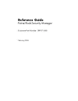
The Lower Cover appears as follows when the Mainboard is removed.
•
Blue callout—Main 3G Antenna cable
•
Yellow callout—Aux 3G Antenna cable
•
Red callout—Main and Aux WLAN Antennas
3.
Remove the Black and White WLAN cables from the cable clips as shown.
Summary of Contents for eMachines eM250
Page 6: ...VI...
Page 10: ...X Table of Contents...
Page 28: ...18 Chapter 1...
Page 45: ...Chapter 2 35 3 Execute MAC BAT to write MAC information to eeprom...
Page 46: ...36 Chapter 2...
Page 52: ...42 Chapter 3 4 Lift the Memory cover up to remove 5 Lift the 3G cover up to remove...
Page 60: ...50 Chapter 3 6 Disconnect the FFC and remove the Keyboard...
Page 70: ...60 Chapter 3 4 Remove the WLAN Board from the Mainboard...
Page 78: ...68 Chapter 3 4 Lift the Thermal Module clear of the Mainboard...
Page 104: ...94 Chapter 3 3 Connect the Camera cable as shown...
Page 126: ...116 Chapter 3 4 Replace the single screw to secure the HDD in place...
Page 155: ...Chapter 5 145 Power board Item Description SW1 Power button LED1 Power LED...
Page 172: ...Appendix A 164 Model Definition and Configuration Appendix A...
Page 180: ...Appendix A 172...
Page 188: ...180 Appendix B...
Page 190: ...182 Appendix C...
Page 194: ...186...