background image

Chapter 3

27

LCD Fails

2

LCD No Back Light

LCD No Display

Inverter Board

Main Board

END

END

LCD Panel

Main Board

LCD Cable

Replacement

Replacement

Replacement

N.G

N.G

N.G

N.G

N.G

N.G

LCD Panel

Summary of Contents for AT4230C

Page 1: ...Acer AT4230C Service Guide PRINTED IN TAIWAN Service guide files and updates are available on the ACER CSD web For more information please refer to http csd acer com tw ...

Page 2: ...II Revision History Please refer to the table below for the updates of LCD TV AT4220A service guide Date Chapter Updates January 15 2007 initial release ...

Page 3: ...ublication may be reproduced transmitted transcribed stored in a retrieval system or translated into any language or computer language in any form or by any means electronic mechanical magnetic optical chemical manual or otherwise without the prior written permission of Acer Incorporated ...

Page 4: ...y Acer Incorporated software described in this manual is sold or licensed as is Should the programs prove defective following their purchase the buyer and not Acer Incorporated its distributor or its dealer assumes the entire cost of all necessary servicing repair and any incidental or consequential damages resulting from any defect in the software Acer is a registered trademark of Acer Incorporat...

Page 5: ... bits and pieces of additional information related to the current topic WARNING Alerts you to any damage that might result from doing or not doing specific actions CAUTION Gives precautionary measures to avoid possible hardware or software problems IMPORTANT Reminds you to do specific actions relevant to the accomplishment of procedures ...

Page 6: ...ill NOT be covered in this generic service guide In such cases please contact your regional offices or the responsible personnel channel to provide you with further technical details 2 Please note WHEN ORDERING FRU PARTS you should check the most up to date information available on your regional web or channel For whatever reason if a part number change is made it will not be noted in the printed ...

Page 7: ...source audio output F type terminal for DVB T digital TV input F type terminal for analog TV CATV input 3 5mm jack for PC audio line input Video Functions NTSC video format support 480i 480p 576p 1080i and 720p format support Built in motion adaptive 3D digital comb filter high performance 5 line comb filter Y C separator Built in dynamic adaptive smoothing filter Built in dynamic temporal frame f...

Page 8: ...tage 90 264V 47 63Hz Input current 3 47A Max Power consumption 347W Max Stand by 3W Max Remote Control Multi function remote control Speaker Internal speaker 10W x 2 stereo adjustable volume Others On screen display adjustment function ISP In System Programming function available for revising driver easily ...

Page 9: ...Chapter 1 3 System Block and Wiring Diagram MAIN Board SPEAKER IR Receiver Key Board Comconner2 Comconnet1 AV 2 AV 1 I O Board D Tuner A Tuner HDMI MODULE DVBT BOARD INVERTER PANEL Module POWER ...

Page 10: ...4 Chapter 1 LCD Main Board Block Diagram ...

Page 11: ... black Surface treatment Anti glare and hard coating 3H Weight 15000g typical Backlight 20 CCFTs Input signal 1 channel LVDS Optimum viewing direction 6 o clock Backlight Power consumption 174W typical CVBS and Y C NTSC 3 58M color system TV Systems NTSC M 3 58M system receivable VHF UHF CATV 181 channels auto preset tuning Full frequency range from 54MHz to 806MHz YUV inputs YCbCr 480i YPbPr 480P...

Page 12: ...dance 75 5 Interface RCA Jack Y Green color U Blue color V Red color Audio input for Y Pb Pr Video Level 500 mVrms Type Stereo R L channels Impedance More than 22K Interface RCA Jack R Red color L White color Audio output for all source Level 500 mVrms typical Type Stereo R L channels Impedance Low Impedance Interface RCA Jack R Red color L White color PC line In Level 500 mVrms Type Stereo R L ch...

Page 13: ...tion FEC 1 2 2 3 3 4 5 6 7 8 Terrestrial Tuner Demodulator Antenna power N A CPU ZR39151 Transport DVB compliant Flash memory 2Mbytes System System memory 16Mbytes Bitstream accepted for Video MPEG 1 Video ISO IEC 11172 2 MPEG 2 Video ISO IEC 13818 2 MPEG 2 profiles levels Supported MP ML SP ML MP LL Frame Field rate 30 60 Hz Video data rate supported 1 15 Mbps Aspect ratio 4 3 and 16 9 with Pan a...

Page 14: ...verter The inverter which is used to light up backlight of LCD panel is designed to meet the requirement of panel s specification Preset Mode Pixel Format Horizontal Frequency KHz Horizontal Polarity Vertical Frequency Hz Vertical Polarity Standard 1 720 400 31 47 70 VGA 2 640 480 31 47 60 VGA 3 640 480 37 861 72 VESA 4 640 480 37 50 75 VESA 5 640 480 43 4 85 VESA 6 800 600 35 156 56 VESA 7 800 60...

Page 15: ...cle 25 3 Vsync f 10Hz 4 duty cycle 25 The power consumption is valid over the specified voltage and frequency range Power consumption is measured from AC source There are no power saving modes for TV SCART1 2 HDMI1 2 AV3 and AV4 inputs 8 800 600 75 46 87 75 9 800 600 85 53 67 85 10 1024 768 60 48 36 60 11 1024 768 70 56 47 70 12 1024 768 75 60 02 75 02 13 1024 768 85 68 67 84 99 14 1280 768 60 15 ...

Page 16: ...component EDID memory will be protected against writing or other corruption through customer accessible electrical connection and required communication channels Password protection use of an unpublished enable register or use of direct electrical connection is acceptable levels of protection provided that the power on Default State is that disabling writing The serial number fields in the EDID wi...

Page 17: ... SOP press Volume Channel Menu and all data will be recalled 7 Physical Specification Overall dimensions 794 H x 1071 W x 311 D mm Overall dimension without stand 744 H x 1071 W x 125 D mm Mass of display with cable 34 5 Kg approx VESA mounting holes Compliant to VESA FPMPMI standard 6 holes 400 mm x 200 mm 6 mm 1 0 pitch threaded in the rear center for ARM ...

Page 18: ...nce measurements and white uniformity measurement Operating temperature Operating humidity 0o C to 40o C 10 to 90 non condensing Storage and Shipping Storage temperature Shipping temperature Storage humidity Shipping temperature 20o C to 60o C 20oC to 60oC 10 to 90 non condensing 10 to 90 non condensing ...

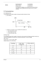
Page 19: ...ied in following specification without any measurable degradation in performance or detectable mechanical or cosmetic damage Filter 330 Hz Dropping way 1 corner 3 edges 6 flats Dropping height see the table below Altitude Operating altitude Shipping altitude Storage altitude 0 to 10 000 feet 0 to 40 000 feet 0 to 40 000 feet Units tested at an altitude up to 12 000 feet must operate at normal cond...

Page 20: ...to handle the module during operation or just after powered off you must take proper precautions against electric shock and must not touch the drive circuit portion and metallic part of module within 10 minutes The capacitors in the drive circuit portion remain temporarily charged even after the unit is powered off If the residual voltage is strong enough it could result in electric shock Thus we ...

Page 21: ...15 Chapter 2 Disassembly Procedures 1 Release the six screws securing the TV Stand 2 Then remove the TV Stand as the arrows indicate 3 Release all the screws marked in red Then remove the TV back cover ...

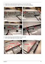
Page 22: ...g the I O box then you can pull out the I O box 5 Release the four screws fastening the HDMI box then you can pull out the HDMI box 6 Release all screws securing the PCB holder 14 screws in total 7 Then remove the PCB holder as the arrows indicate ...

Page 23: ...pter 2 8 Release the four screws securing the I O transfer board and slightly detach the I O transfer board 9 Release the two screws holding the HDMI transfer board and slightly detach the HDMI transfer board ...

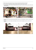
Page 24: ...e power board 12 Release the five screws holding the main board and the I O board Then remove the main board and the power board altogether 13 Release the four screws fastening the right speaker Disconnect the right speaker cable then remove the right speaker 14 Release the four screws holding the left speaker Disconnect the left speaker cable then remove the left speaker ...

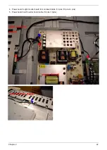
Page 25: ...ch the function board 16 Detach function key 17 Release the two screws holding the IR board then detach the IR board 18 Release the six screws holding the TV stand bracket then remove the TV stand bracket 19 Release the four screws holding the PCB tray then remove the PCB tray ...

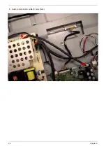
Page 26: ...Chapter 2 20 20 Release the 8 screws marked in red then remove the right and the left LCD brackets 21 Release the screws holding the LCD then you can remove the LCD ...

Page 27: ...fer to this section to reconnect all cables when you do the assembly 1 LVDS cable 2 Power board to main board to I O board cable 14 pins 10 pins 8 pins 3 Speaker cables red blace cable connected to right speaker white black connected to left speaker ...

Page 28: ...Chapter 2 22 4 Power board to right inverter board to main board cable 14 pins 10 pins 4 pins 5 Power board to left inverter board cable 12 pins 10pins ...

Page 29: ...23 Chapter 2 6 Audio to main board cable 8 pins 7pins ...

Page 30: ...Chapter 2 24 7 Main board to function key board to IR board cable 10 pins 9 pins 8 pins The other two ends of this cable link to function key board and IR board ...

Page 31: ... the symptoms by attempting to re create the failure by running the diagnostic test or by repeating the same operation 3 Disassemble and assemble the unit without any power sources 4 If any problem occurs you can perform visual inspection before you follow this chapter s instructions You can check the following Power cords are properly connected and secured There are no obvious shorts or opens The...

Page 32: ...26 Chapter 3 Symptoms No Power on 1 Power Cord Power Cable Power Board Main Board END Replacement Replacement Replacement Replacement N G N G N G N G ...

Page 33: ...Chapter 3 27 LCD Fails 2 LCD No Back Light LCD No Display Inverter Board Main Board END END LCD Panel Main Board LCD Cable Replacement Replacement Replacement N G N G N G N G N G N G LCD Panel ...

Page 34: ...28 Chapter 3 ATV Channel Fails 3 Button Board I O Board Main Board END Replacement Replacement Replacement N G N G N G ...

Page 35: ...Chapter 3 29 DDC POP PIP Fails 4 Main Board END Replacement N G ...

Page 36: ...30 Chapter 3 Remote Control Fails 5 IR Cable IR board Main Board END Replacement Replacement Replacement N G N G N G ...

Page 37: ...Chapter 3 31 RF No Signal HDMI Fails 6 IO Board Main Board END Replacement Replacement N G N G Translation Board Replacement N G ...

Page 38: ...32 Chapter 3 Unit Hang Up Suddenly 8 Power Board Main Board END Replacement Replacement N G N G ...

Page 39: ...Chapter 3 33 AV1 AV2 AV3 Speaker No Sound 9 Speck Cable Speaker Main Board IO Board END Replacement Replacement Replacement Replacement N G N G N G N G ...

Page 40: ...34 Chapter 3 Can Not Enter Factory Mode 10 Button Cable Button Board IO Board Main Board END Replacement Replacement Replacement Replacement N G N G N G N G ...

Page 41: ...Chapter 3 35 VGA No Display 11 VGA Cable EDID CODE END Replacement Write EDID N G N G MB Replacement N G ...

Page 42: ...36 Chapter 3 HDMI No Display 12 HDMI Cable EDID CODE END Replacement Write EDID N G MB Replacement N G HDMI BOX Replacement N G N G ...

Page 43: ...Chapter 3 37 DVT No Display 13 Cable of DVT IO BOX END Replacement Replacement N G Cable for DTV PW Replacement N G Translation Board Replacement N G MB Replacement N G DTV Board Replacement N G N G ...

Page 44: ...38 Chapter 3 AV CABS No Display 14 CVBS cable IO BOX END Replacement Replacement N G MB Replacement N G Translation Board Replacement N G N G ...

Page 45: ...Chapter 3 39 YUV No Display 15 YUV cable IO BOX END Replacement Replacement N G MB Replacement N G Translation Board Replacement N G N G ...

Page 46: ...is made it will NOT be noted on the service guide For Acer authorized service providers your Acer office may have a different part number code from those given in the FRU list of this printed service guide You MUST use the local FRU list provided by your regional Acer office to order FRU parts for repair and service of customer machines Note To scrap or to return the defective parts you should fol...

Page 47: ...ANEL AUO 12P 10P 2A 50 M34V7 002 INVERTER CABLE INVERTER R TO POWER TO MB CABLE ASSY HX4E INV AU 14P 10P 4P 2A 50 M34V7 003 SPEAKER CABLE CABLE ASSY HH2 SPEAKER 2P 3P 4P 1A 50 M12V7 005 CABLE MB TO KEY TO IR CABLE ASSY HV4 MB IR BTN 10 9 8 REV1A 50 M34V7 004 CABLE POWER B TO MB TO DT CABLE ASSY HX7 P MB DT 14P 10P 8P REV1A 50 M3507 004 CABLE AUDIO TO POWER BOARD 8P 7P CABLE ASSY HX4 AUDIO POWER 8P...

Page 48: ...3A 47 M25V7 006 EMI GASKET LVDS HX4 GBHX4002 3A EMI GASKET LVDS HX4 GBHX4002 3A 47 M34V7 004 EMI GASKET UP HX4 GBHX4003 3A EMI GASKET UP HX4 GBHX4003 3A 47 M34V7 005 EMI GASKET DOWN HX4 GBHX4004 3A EMI GASKET DOWN HX4 GBHX4004 3A 47 M34V7 006 EMI GASKET POWER HX4 GBHX4005 3A EMI GASKET POWER HX4 GBHX4005 3A 47 M34V7 007 EMI CONTACT PAD HX4 JXHX4001 3A EMI CONTACT PAD HX4 JXHX4001 3A 47 M34V7 003 B...

Page 49: ...M04V7 003 PACKING EPE BAG AH4 HAAH4001 3A 1200 9 50 EPE BAG AH4 HAAH4001 3A 1200 950 47 M34V7 013 EPS FOAM BASE R AH4 HBAH4001 EPS FOAM BASE R AH4 HBAH4001 3A 47 M4207 001 EPS FOAM BASE L AH4 HBAH4002 EPS FOAM BASE L AH4 HBAH4002 3A 47 M4207 002 EPS FOAM TOP R AH4 HBAH4003 EPS FOAM TOP R AH4 HBAH4003 3A 47 M4207 003 EPS FOAM TOP L AH4 HBAH4004 EPS FOAM TOP L AH4 HBAH4004 3A 47 M4207 004 EPE BAG AH...

Page 50: ... 9 STAND ASSY HV4 STAND ASSY 60 M34V7 003 1 10 PCB SHIELDING AH4T SHIELDING ASSY 60 M4207 002 1 11 BACK COVER ASSY AH4T BACK COVER ASSY 60 M34V7 002 1 12 STAND COVER STAND COVER HX4 EAHX4004 REV3B 42 M34V7 001 1 13 POWER BOARD PWR 291W DPS 291AP A 90 264VAC 55 M34V7 001 1 14 MAIN BOARD FOR AUO NTSC TWN HH7T M B ASSY TWN FOR HV4T 55 M4207 004 1 15 SPEAKER ASSY R SPEAKER ASSY HX4E FS 0000085AA 23 M3...

Page 51: ......

Reviews: