15
Remote Control & OSD Operating instructions
Using the Remote Control
.
Chapter 3
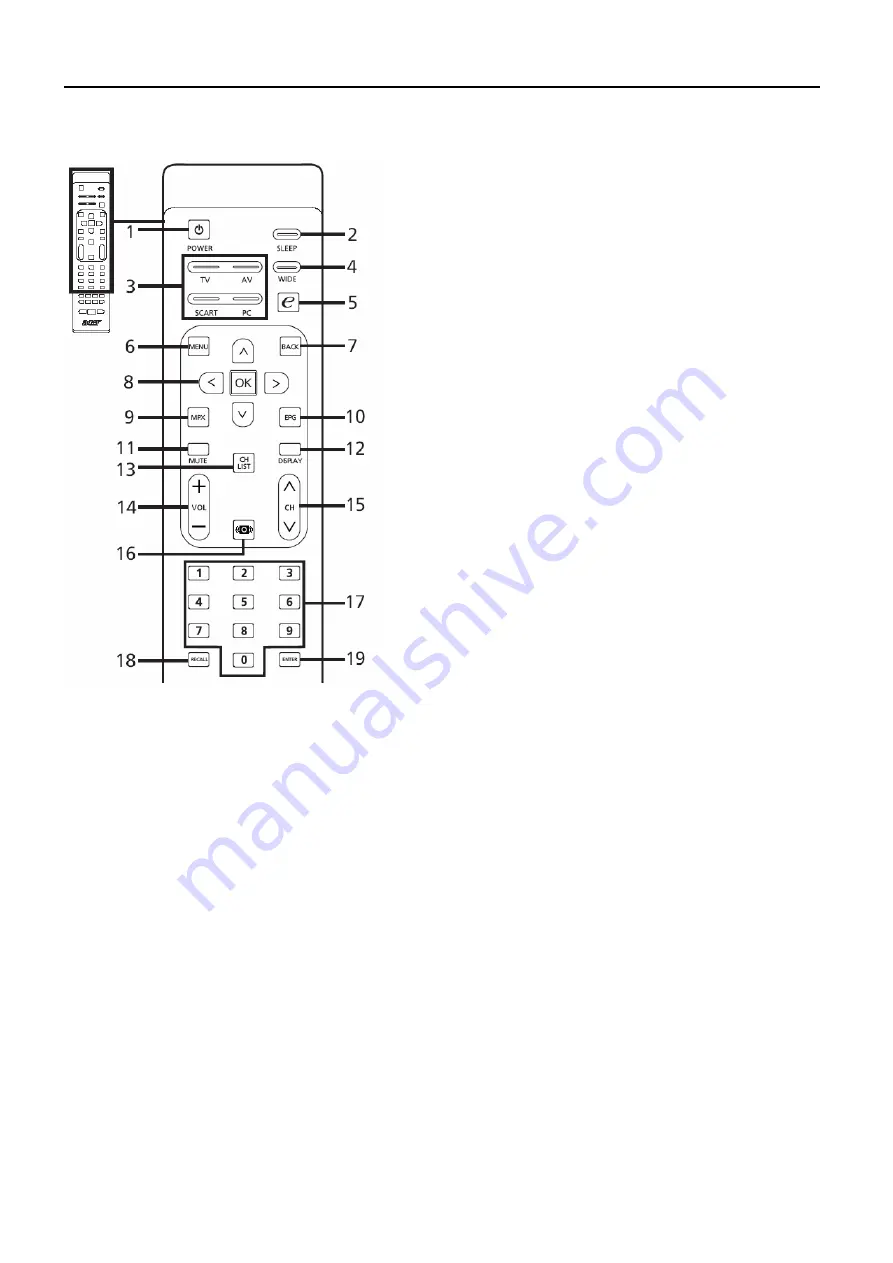
5 e (Empowering Technology)
Press to activate Acer Empowering
Technology. See page 25.
6 MENU
Press to open or close the Menu.
7 Back
Press to back to previous Menu.
8 Directional keys/OK
9 MPX
Press to select the audio type,
displayed in the top right-hand
corner(mono, stereo, bilingual).
10 EPG
Press to launch Electronic Programme
Guide (EPG) mode
(Digital TV mode only).
11 MUTE
Press to toggle audio on and off.
12 DISPLAY
Press to display or change input/
channel information (dependent on
input/source type).
13 CH LIST
Press to launch the channel list. See
page 40.
14 VOL (+/-)
Press to increase or decrease the
volume.
15 CH (up/down)
Press to sequentially select the TV
channel.
16 Sound
Press to turn audio mode to Surround
mode.
17 Number keys
.
18 RECALL
Press to return to the previous channel.
19 ENTER
Press to confirm channel number
selection.
1 POWER
Press to turn your TV on/off.
2 SLEEP
Press to set a time period after which
the TV will switch itself to standby
( 5, 30, 45, 60, 90 or 20 minutes).
3 Input buttons (TV/AV/SCART/PC)
Press to select correct input mode.
4 WIDE
Press to toggle scaling mode
between Wide detect, 4:3, 6:9,
Full*, Panorama and Letterbox , 2, 3
modes.
PS: The 26" and 32" models does not support Full mode.
Summary of Contents for AT3245
Page 1: ...1 Acer AT3245 AT3246 Service Guide ...
Page 7: ...7 Monitor Features General Specifications Chapter 1 ...
Page 8: ...8 ...
Page 11: ...11 Factory Preset Display Modes VGA HDMI Input Signal Reference Chart ...
Page 13: ...13 Electrical Characteristics Optical Specifications Test Conditions Optical Specifications ...
Page 14: ...14 Connecting Peripherals Front panel controls Chapter 2 ...
Page 17: ...17 Using the OSD Menus ...
Page 18: ...18 ...
Page 19: ...19 ...
Page 20: ...20 ...
Page 21: ...21 ...
Page 22: ...22 ...
Page 23: ...23 ...
Page 24: ...24 ...
Page 27: ...27 3 Remove 4 screws to remove the bkt vesa top 4 Release the connectors ...
Page 28: ...28 5 Remove the speakers 6 Remove the main board power board ...
Page 30: ...30 10 Remove the bezel 11 Remove the 6 screws to release the panel ...
Page 38: ...38 ...
Page 40: ...40 IV Click Upgrade button Waiting for Finished message V Main board Power Off _ On ...
Page 44: ...44 Exploded Diagram Model AT3245 AT3246 ...
Page 45: ...45 EDID Data DDC DATA for For D SUB Input EDID data 128 bytes ...
Page 46: ...46 PCB Layout Main Board Layout Chapter 9 ...
Page 47: ...47 ...
Page 48: ...48 Power Board ...
Page 49: ...49 Key Board IR board ...


