


System Utilities
2-7
0
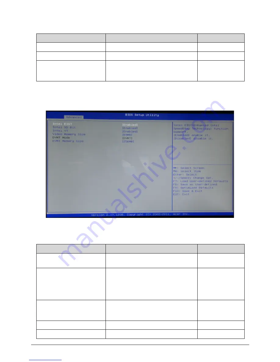
Advanced -> Advanced Chipset Configuration
0
SATA Port (AHCI Port) 2
SATA Port (AHCI Port) 2 information.
N/A
Bootup Num-Lock
Selects power on state for Num Lock.
Off/On
USB Beep Message
Enables or disables BIOS to display
error beeps or messages during USB
device enumeration.
Disabled/Enabled
Table 2-3.
Parameter
Description
Options
Intel EIST
Intel EIST (Enhanced Intel Speed Step
Technology) function support.
Disabled/Enabled
Intel XD Bit
XD can prevent certain classes of
malicious buffer overflow attacks when
combined with a supporting OS.
(Windows XP SP2, SUSE Linux 9.2,
RedHat Enterprise 3 Update)
Disabled/Enabled
Intel VT
When enabled, a VMM can utilize the
additional hardware capabilities provided
by Virtualization Technology.
Disabled/Enabled
Video Memory Size
Video Share Memory Size.
64MB/128MB
DVMT Mode
DVMT Mode information.
DVMT
Table 2-2.
Parameter
Description
Options
Summary of Contents for Aspire Z5770
Page 1: ...Acer AZ5770 AZ5771 SERVICEGUIDE ...
Page 2: ...ii ...
Page 6: ...ii vi ...
Page 7: ...CHAPTER 1 Hardware Specifications ...
Page 26: ...1 20 Hardware Specifications and Configurations M B Placement 0 ...
Page 28: ...1 22 Hardware Specifications and Configurations Internal header pin definition 0 ...
Page 29: ...Hardware Specifications and Configurations 1 23 Block Diagram 0 ...
Page 30: ...1 24 Hardware Specifications and Configurations ...
Page 31: ...CHAPTER 2 System Utilities ...
Page 48: ...2 18 System Utilities 8 Flash BIOS is finished ...
Page 52: ...2 22 System Utilities 10 Flash BIOS is finished ...
Page 61: ...System Utilities 2 31 12 Select Yes and press Enter key 13 Flash BIOS is finished ...
Page 64: ...2 34 System Utilities 11 Select Yes and press Enter key 12 Flash BIOS is finished ...
Page 67: ...System Utilities 2 37 ...
Page 71: ...System Utilities 2 41 ...
Page 72: ...2 42 System Utilities ...
Page 73: ...CHAPTER 3 System Disassembly and Assembly ...
Page 76: ...3 4 ...
Page 84: ...3 12 System Disassembly and Assembly First open one top side then open the other top side ...
Page 95: ...System Disassembly and Assembly 3 23 Removing the Display Card 0 ...
Page 102: ...3 30 System Disassembly and Assembly ID Size Quantity Screw Type M3X5L B 3 ...
Page 105: ...System Disassembly and Assembly 3 33 Removing the CPU 0 ...
Page 108: ...3 36 System Disassembly and Assembly ID Size Quantity Screw Type M3X5L B 3 ...
Page 120: ...3 48 System Disassembly and Assembly Unplug the LCD power cable Take out the LCD with bracket ...
Page 130: ...3 58 System Disassembly and Assembly Lock all the latch Plug the LVDS cable ...
Page 148: ...3 76 System Disassembly and Assembly Lock 2 VGA locks ...
Page 165: ...System Disassembly and Assembly 3 93 ID Size Quantity Screw Type M3X5L B 1 N A 4 ...
Page 171: ...System Disassembly and Assembly 3 99 Install the hinge cover ...
Page 175: ...CHAPTER 4 Troubleshooting ...
Page 190: ...4 16 Troubleshooting Pressing the 25 calibration points in proper hole by using the stylus ...
Page 194: ...4 20 Troubleshooting ...
Page 195: ...CHAPTER 5 Jumper and Connector Locations ...
Page 196: ...5 2 Jumper Setting 5 4 Setting Jumper 5 4 ...
Page 197: ...Jumper and Connector Locations 5 3 Jumper and Connector Locations ...
Page 200: ...5 6 Jumper and Connector Locations ...
Page 201: ...CHAPTER 6 FRU List ...
Page 202: ...6 2 AZ5770 AZ5771 Exploded Diagrams 6 4 FRU List 6 7 ...


