


Chapter 2
31
Setting a Password
Follow these steps as you set the user or the supervisor password:
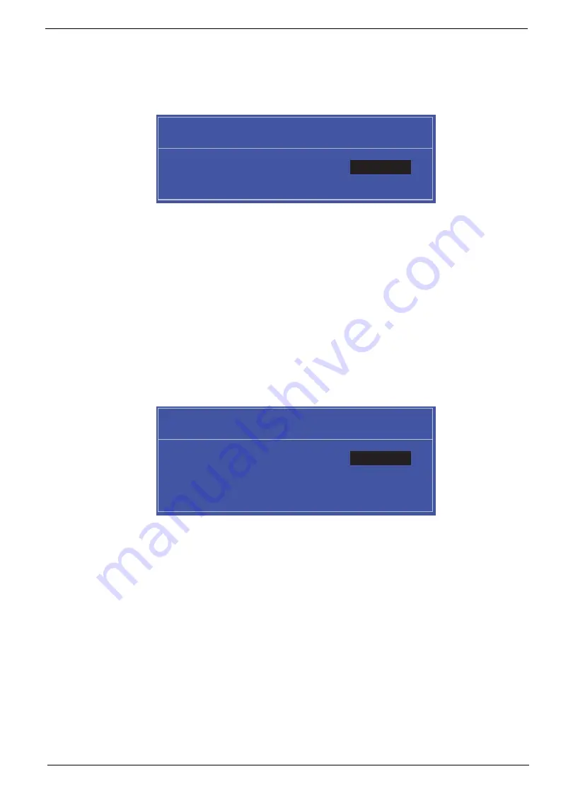
1.
Use the
↑
and
↓
keys to highlight the Set Supervisor Password parameter and press the
Enter
key. The
Set Supervisor Password box appears:
2.
Type a password in the “Enter New Password” field. The password length can not exceeds 8
alphanumeric characters (A-Z, a-z, 0-9, not case sensitive). Retype the password in the “Confirm New
Password” field.
IMPORTANT:
Be very careful when typing your password because the characters do not appear on the screen.
3.
Press
Enter
.
After setting the password, the computer sets the User Password parameter to “Set”.
4.
If desired, you can opt to enable the Password on boot parameter.
5.
When you are done, press F10 to save the changes and exit the BIOS Setup Utility.
Removing a Password
Follow these steps:
1.
Use the
↑
and
↓
keys to highlight the Set Supervisor Password parameter and press the
Enter
key. The
Set Password box appears:
2.
Type the current password in the Enter Current Password field and press
Enter
.
3.
Press
Enter
twice
without
typing anything in the Enter New Password and Confirm New Password fields.
The computer then sets the Supervisor Password parameter to “Clear”.
4.
When you have changed the settings, press
u
to save the changes and exit the BIOS Setup Utility.
S e t S u p e r v i s o r P a s s w o r d
E n t e r N e w P a s s w o r d [ ]
[ ]
C o n f i r m N e w P a s s w o r d [ ]
S e t S u p e r v i s o r P a s s w o r d
E n t e r C u r r e n t P a s s w o r d [ ]
[ ]
E n t e r N e w P a s s w o r d [ ]
C o n f i r m N e w P a s s w o r d [ ]
[ ]
Summary of Contents for Aspire One D255 Series
Page 6: ...VI ...
Page 10: ...X Table of Contents ...
Page 36: ...26 Chapter 1 ...
Page 53: ...Chapter 2 43 3 Execute MAC BAT to write MAC information to eeprom ...
Page 62: ...52 Chapter 3 5 Unlock the FPC 6 Remove the FPC and the keyboard ...
Page 90: ...80 Chapter 3 8 Remove the LCD module from the chassis ...
Page 133: ...Chapter 3 123 2 Push the battery lock latch in the direction shown to secure the battery ...
Page 134: ...124 Chapter 3 ...
Page 156: ...146 Chapter 4 ...
Page 264: ...254 Chapter 3 ...
Page 270: ...260 Appendix C ...