


Jumper and Connector Locations
5-7
Clearing Password Check and BIOS Recovery
0
This section provides procedures for:
Clearing the BIOS passwords
Performing a BIOS recovery
Clearing the BIOS Passwords
0
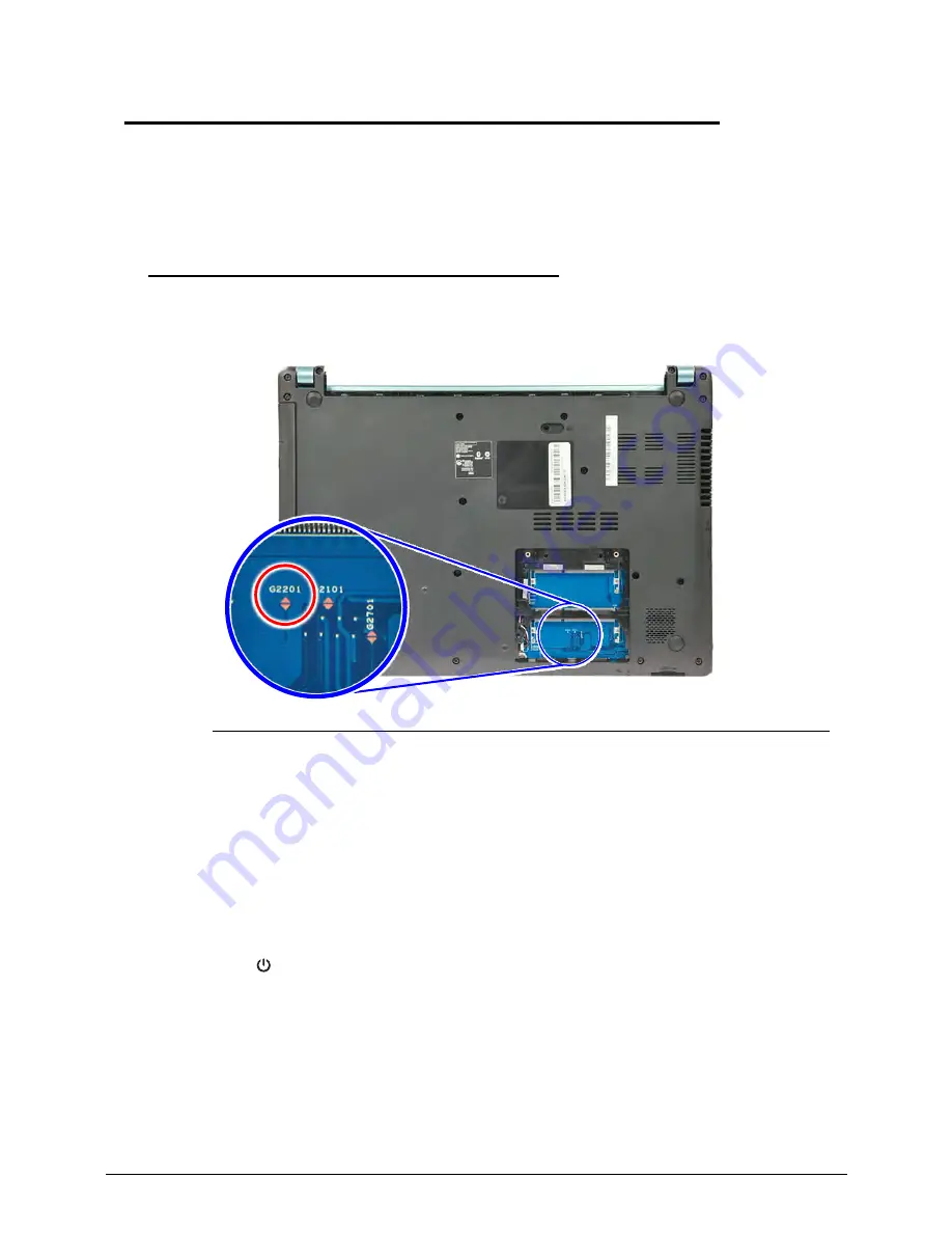
To clear a lost BIOS password (user or supervisor password), you need to short the clear
password hardware gap (G2201) located on the mainboard.
Figure 2-5.
G2201 Hardware Gap
1.
Shut down the computer and disconnect the AC adapter and all other peripherals from the
computer.
2.
Remove the battery pack and DIMM cover.
3.
If the DIMM2 slot is occupied, remove the installed DIMM module and locate the G2201
gap.
4.
Use an electrical conductivity tool to short the two contacts on the hardware gap together.
5.
While resting the tool on the two contacts, plug one end of the AC adapter into the DC-in
jack and plug one end to an electrical outlet.
6.
Press the button to turn on the computer.
7.
After the BIOS POST, remove the tool from the hardware gap.
8.
Reinstall the DIMM module, DIMM cover and battery pack.
9.
Turn on the computer and press
F2
during bootup to access the
Setup Utility
. If no
password prompt appears, the BIOS passwords have been cleared. If the prompt
appears, repeat steps 4-9 until the BIOS passwords have been cleared.
10. Press
F9
to load the system defaults.
11. Press
F10
to save the changes you made and close the Setup Utility.
Summary of Contents for Aspire MS2360
Page 1: ...Aspire MS2360 SERVICEGUIDE ...
Page 10: ...x ...
Page 11: ...CHAPTER 1 Hardware Specifications ...
Page 14: ...1 4 ...
Page 60: ...1 50 Hardware Specifications and Configurations ...
Page 61: ...CHAPTER 2 System Utilities ...
Page 79: ...CHAPTER 3 Machine Maintenance ...
Page 82: ...3 4 ...
Page 92: ...3 14 Machine Maintenance 6 Pry the ODD bezel off the module Figure 3 11 ODD Bezel ...
Page 116: ...3 38 Machine Maintenance 4 Detach the LCD module from the lower case Figure 3 48 LCD Module ...
Page 158: ...3 80 Machine Maintenance ...
Page 159: ...CHAPTER 4 Troubleshooting ...
Page 190: ...4 32 Troubleshooting ...
Page 191: ...CHAPTER 5 Jumper and Connector Locations ...
Page 200: ...5 10 Jumper and Connector Locations ...
Page 201: ...CHAPTER 6 FRU List ...
Page 202: ...6 2 Aspire MS2360 Exploded Diagrams 6 4 Main Assembly 6 4 LCD Assembly 6 6 FRU List 6 7 ...
Page 225: ...CHAPTER 7 Test Compatible Components ...
Page 226: ...7 2 Microsoft Windows 7 Environment Test 7 3 ...
Page 233: ...CHAPTER 8 Online Support Information ...
Page 234: ...8 2 Online Support Information 8 3 ...
Page 236: ...8 4 Online Support Information ...