10
Chapter 2
Entering the BIOS Setup Utility
Before you begin, prepare the following:
Wrist grounding strap and conductive mat for preventing electrostatic discharge
Philips screwdriver
Debug card - Refer to page 44 for details about the debug card.
Debug card cable
1.
Turn off the computer and all attached devices.
2.
Remove the cover. See “Removing the System Cover” on page 25.
3.
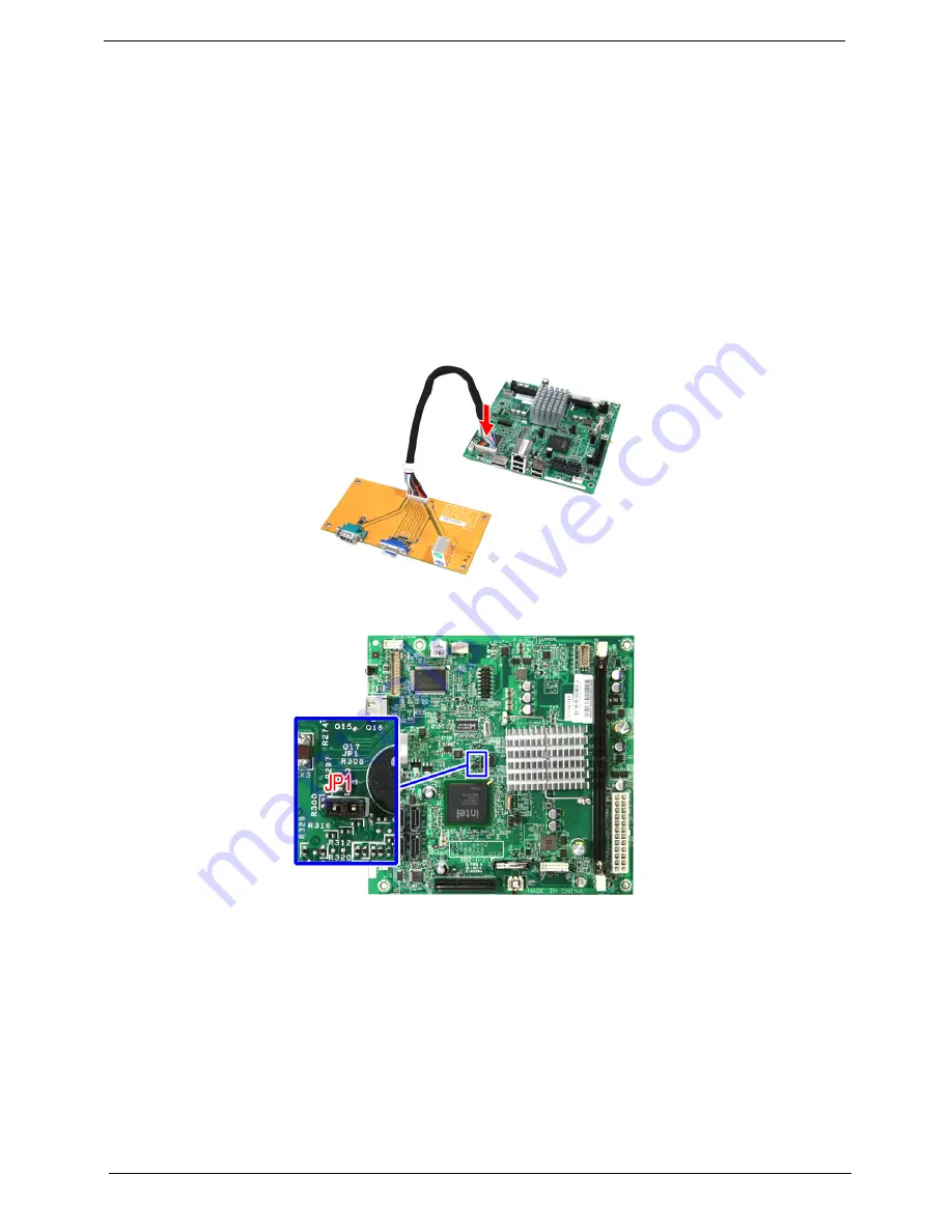
Connect the debug card cable to the debug card cable connector on the mainboard.
4.
Locate the JP1 Debug/User mode jumper on the mainboard.
5.
Close the jumper to enable system for debug mode.
6.
Connect the power cable to the rear panel.
7.
Connect a PS/2 keyboard to the PS/2 keyboard port on the debug card.
8.
Connect a monitor to the VGA port on the debug card.
9.
Restart the system.
10.
Turn on the monitor.
11.
During POST, press <
Delete
>.
If you fail to press <
Delete
> before POST is completed, you will need to restart the system.
When the Setup Utility screen displays, use the left and right arrow keys to move through the menus.
Summary of Contents for Aspire EASYSTORE H341
Page 1: ...Aspire easyStore H341 H342 Service Guide PRINTED IN TAIWAN ...
Page 16: ...8 Chapter 1 ...
Page 26: ...18 Chapter 2 ...
Page 31: ...Chapter 3 23 3 Flex the carrier handle 4 Slide the hard drive carrier out of the HDD bay ...
Page 35: ...Chapter 3 27 4 Pull the bezel away from the chassis ...
Page 40: ...32 Chapter 3 8 Lift the backplane board off the bracket ...
Page 62: ...54 Chapter 4 ...
Page 63: ...Chapter 5 55 System Block Diagram System Block Diagram and Board Layout Chapter 5 ...
Page 66: ...58 Chapter 5 ...
Page 68: ...60 Chapter 6 Exploded Diagram ...


