


Hardware Specifications and Configurations
1-5
Committee)
TV-tuner I/O:
RF-in jack for digital/TV antenna cable input
Card reader
0
Multi-in-1 card reader, supporting:
MultiMediaCard (MMC)
SD Card
SDHC Card
Memory Stick
Memory Stick PRO Duo
Memory Stick PRO-HG Duo
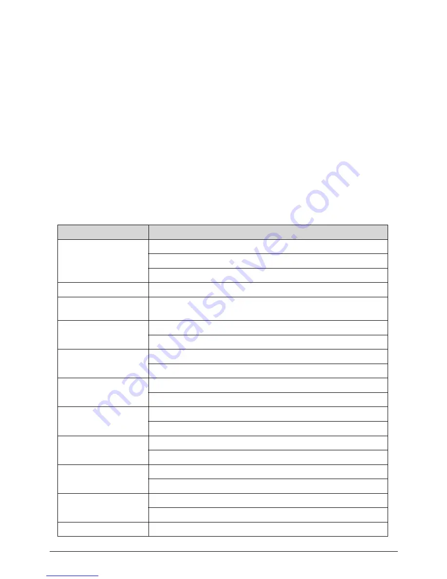
Table 1-1. Cardreader Test List
Supporting Type
Detail
Secure Digital (SD)
(SDHC)
Transcend SDHC Class10 16GB
Transcend SDHC 4GB
ADATA SDHC Class6 8GB
Mini SD
SanDisk mini SD 1GB
Multi Media Card
(MMC)
PLEOMAX 1GB
RS-MMC
SanDisk RS-MMC 512MB
A-DATA RS-MMC 256MB
MMC Plus
A-DATA MMC plus 256MB
Kingston MMC plus 512MB
MMC Mobile
SanDisk MMC Mobile 256MB
Kingston MMC Mobile 256MB
Memory Stick (MS)
SanDisk MS 128MB
SONY MS 128MB
Memory Stick Pro (MS
Pro)
SONY MS PRO 512MB
SONY MS PRO 1GB
Memory Stick Pro Duo
(MS Pro Duo)
SONY MS PRO DUO 4GB
SanDisk MS PRO DUO 4GB
Memory Stick Duo (MS
Duo)
SONY MS DUO 64MB
SONY MS DUO 128MB
Micro SD
Kinston Micro SD 4GB
Summary of Contents for Aspire AZS600_P
Page 1: ...Acer AZS600_Pt AZS600_P SERVICEGUIDE ...
Page 4: ...iv ...
Page 8: ...ii viii ...
Page 9: ...CHAPTER 1 Hardware Specifications ...
Page 29: ...Hardware Specifications and Configurations 1 21 M B Placement 0 ...
Page 32: ...1 24 Hardware Specifications and Configurations Block Diagram 0 ...
Page 33: ...CHAPTER 2 System Utilities ...
Page 61: ...System Utilities 2 29 1 Check ME status with MEInfo Utility and ManufacturingMode is Disabled ...
Page 69: ...System Utilities 2 37 12 Select Yes and press Enter key 13 Flash BIOS is finished ...
Page 72: ...2 40 System Utilities ...
Page 77: ...CHAPTER 3 System Disassembly and Assembly ...
Page 80: ...3 4 ...
Page 83: ...3 7 Disassembly Flowchart 0 Figure 3 1 Disassembly Flowchart ...
Page 85: ...3 9 Table 3 2 Screws Step Screw Quantity Screw Type Stand Removal M4 6 3 ...
Page 87: ...3 11 Figure 3 6 ODD Bezel ...
Page 94: ...3 18 Figure 3 18 VESA Support Bracket ...
Page 103: ...3 27 Figure 3 34 Speaker ...
Page 105: ...3 29 Figure 3 37 Heatsink ...
Page 108: ...3 32 Figure 3 42 Convert Board ...
Page 110: ...3 34 Figure 3 45 OSD Board ...
Page 112: ...3 36 Figure 3 48 VGA Card ...
Page 114: ...3 38 Figure 3 51 VGA Bracket ...
Page 116: ...3 40 Figure 3 54 WLAN Card Figure 3 55 WLAN Card ...
Page 133: ...3 57 Figure 3 84 Base Pan ...
Page 138: ...3 62 Reassembly Procedure 0 Reassembly Flowchart 0 Figure 3 92 Reassembly Flowchart ...
Page 140: ...3 64 Table 3 26 Screws Step Screw Quantity Screw Type Front Bezel Replacement M3 5 10 ...
Page 158: ...3 82 Figure 3 122 Replace CPU Step 2 Figure 3 123 Replace CPU Step 3 ...
Page 159: ...3 83 Figure 3 124 Replace CPU Step 4 Figure 3 125 Replace CPU Step 5 ...
Page 160: ...3 84 Figure 3 126 Replace CPU Step 6 ...
Page 165: ...3 89 Figure 3 133 WLAN Card ...
Page 167: ...3 91 Figure 3 136 VGA Holder ...
Page 171: ...3 95 Figure 3 143 Conductive Fabric ...
Page 188: ...3 112 Table 3 47 Screws Step Screw Quantity Screw Type PCT Touch Cable Replacement M3 5 1 ...
Page 193: ...3 117 Figure 3 179 ODD Bezel ...
Page 195: ...CHAPTER 4 Troubleshooting ...
Page 204: ...4 10 Troubleshooting 3 Once firmware update is completed press any key to reboot the system ...
Page 210: ...4 16 Troubleshooting Click the 25 points shown in the screen with the touch pen ...
Page 213: ...Troubleshooting 4 19 ...
Page 218: ...4 24 Troubleshooting ...
Page 219: ...CHAPTER 5 Jumper and Connector Locations ...
Page 220: ...5 2 Jumper Setting 5 5 Setting Jumper 5 5 ...
Page 221: ...Jumper and Connector Locations 5 3 Jumper and Connector Locations ...
Page 224: ...5 6 Jumper and Connector Locations ...
Page 225: ...CHAPTER 6 FRU List ...
Page 226: ...6 2 AZS600_Pt Exploded Diagrams 6 4 FRU List 6 7 ...


