


Chapter 1
11
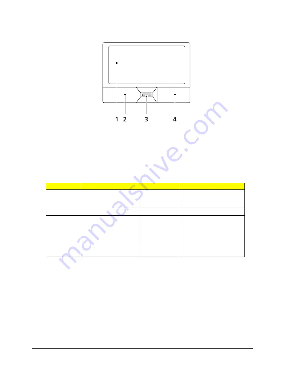
Touch Pad Basics (with fingerprint reader)
The following items show you how to use the Touch Pad with Acer Bio-Protection fingerprint reader:
•
Move your finger across the Touch Pad (2) to move the cursor.
•
Press the left (1) and right (4) buttons located beneath the Touch Pad to perform selection and
execution functions. These two buttons are similar to the left and right buttons on a mouse.
Tapping on the Touch Pad is the same as clicking the left button.
•
Use Acer Bio-Protection fingerprint reader (3) supporting Acer FingerNav 4-way control function
(only for certain models) or the 4-way scroll (3) button (only for certain models) to scroll up or down
and move left or right a page. This fingerprint reader or button mimics your cursor pressing on the
right scroll bar of Windows applications.
NOTE:
When using the Touch Pad, keep it - and your fingers - dry and clean. The Touch Pad is sensitive to
finger movement; hence, the lighter the touch, the better the response. Tapping too hard will not
increase the Touch Pad’s responsiveness.
Function
Left Button (1)
Right Button (3)
Main Touch Pad (2)
Execute
Quickly click twice.
Tap twice (at the same speed
as double-clicking a mouse
button).
Select
Click once.
Tap once.
Drag
Click and hold, then use
finger on the Touch Pad to
drag the cursor.
Tap twice (at the same speed
as double-clicking a mouse
button); rest your finger on
the Touch Pad on the second
tap and drag the cursor.
Access
context menu
Click once.
Summary of Contents for Aspire 7730 Series
Page 6: ...VI ...
Page 14: ...4 Chapter 1 System Block Diagram ...
Page 36: ...26 Chapter 1 Normal voltage 11 1V Charge voltage 16 0V Item Specification ...
Page 84: ...74 Chapter 3 9 Grasp the cover by the opposite edge and lift up to remove the Upper Cover ...
Page 90: ...80 Chapter 3 4 Remove the module as shown Step Size Quantity Screw Type Speaker M2 3 NL 2 ...
Page 94: ...84 Chapter 3 4 Lift the ExpressCard module away from the upper cover ...
Page 105: ...Chapter 3 95 4 Remove the LCD brackets by pulling away from the LCD Panel as shown ...
Page 108: ...98 Chapter 3 8 Connect the left and right Inverter cables 9 Connect the camera cable ...
Page 136: ...126 Chapter 3 ...
Page 171: ...Chapter 6 161 Lower Cover Number Description Part Number 1 2 3 4 ...
Page 172: ...162 Chapter 6 LCD Panel Number Description Part Number 1 2 3 4 5 6 7 8 9 10 ...
Page 202: ...Appendix A 192 ...
Page 208: ...198 Appendix C ...


