60
Chapter 3
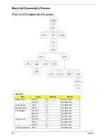
Main Unit Disassembly Process
Main Unit Disassembly Flowchart
Screw List
Step
Screw
Quantity
Part No.
Switch Cover
M2.5*3
4
86.T25V7.012
M2.5*6.5
5
86.ARE07.001
Switch Board
M2*3
2
86.ARE07.002
Modem Module
M2*3
2
86.ARE07.002
LCD Module
M2.5*6.5
2
86.ARE07.001
M2.5*6.5
4
86.ARE07.001
M2.5*3
1
86.T25V7.012
Upper Cover
M2.5*6.5
11
86.ARE07.001
M2*3
1
86.ARE07.002
M2.5*3
4
86.T25V7.012
Touch Pad Bracket
M2*3
4
86.ARE07.002
Summary of Contents for Aspire 7230
Page 6: ...VI ...
Page 10: ...X Table of Contents ...
Page 92: ...82 Chapter 3 4 Grasp the Subwoofer Module and lift it up to remove ...
Page 94: ...84 Chapter 3 4 Lift the ExpressCard module away from the upper cover ...
Page 101: ...Chapter 3 91 4 Lift up the bezel and remove it from the LCD Module ...
Page 105: ...Chapter 3 95 5 Grasp the panel by both ends and lift to remove ...
Page 107: ...Chapter 3 97 4 Remove the LCD brackets by pulling away from the LCD Panel as shown ...
Page 110: ...100 Chapter 3 8 Connect the left and right Inverter cables 9 Connect the camera cable ...
Page 118: ...108 Chapter 3 4 Connect the two FFC cables as shown 5 Connect the cable as shown ...
Page 206: ...196 Appendix C ...

