


System Utilities
2-11
Removing a Password
0
Perform the following:
1.
Use the
and
keys to highlight
Set Supervisor Password
and press Enter. The
Set Supervisor Password
dialog box is shown. (Figure 2-7)
Figure 2-7. Removing a Password: Set Supervisor Password
2.
Type current password in
Enter Current Password
field and press Enter.
3.
Press Enter twice
without
typing anything in
Enter New Password
and
Confirm New
Password
fields. Computer will set
Supervisor Password
parameter to
Clear
.
4.
Press F10
to save changes and exit the BIOS Setup Utility.
Changing a Password
0
1.
Use the
and
keys to highlight
Set Supervisor Password
and press Enter. The
Set Supervisor Password
dialog is shown. (Figure 2-8)
Figure 2-8. Changing a Password: Set Supervisor Password
2.
Type current password in
Enter Current Password
field and press Enter.
3.
Type new password in
Enter New Password
field and press Enter.
4.
Retype new password in
Confirm New Password
field and press Enter.
5.
If new password and confirm new password strings match, The
Setup Notice
dialog is
shown (
). If it is not shown, go to step 6.
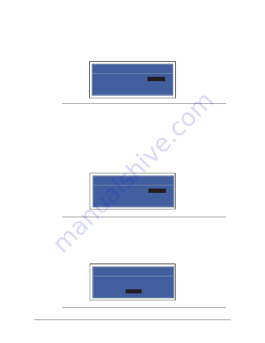
Figure 2-9. Changing a Password: Setup Notice
Set Supervisor Password
Enter Current Password [ ]
Enter Current Password
Enter New Password [ ]
Confirm New Password [ ]
Set Supervisor Password
Enter Current Password [ ]
Enter Current Password
Enter New Password [ ]
Confirm New Password [ ]
Setup Notice
Changes have been saved.
[Continue]
Continue
Summary of Contents for Aspire 5951G
Page 1: ...Aspire 5951G SERVICE GUIDE ...
Page 10: ...x ...
Page 11: ...CHAPTER 1 Hardware Specifications ...
Page 14: ...1 4 ...
Page 66: ...1 56 Hardware Specifications and Configurations ...
Page 67: ...CHAPTER 2 System Utilities ...
Page 96: ...2 30 System Utilities ...
Page 97: ...CHAPTER 3 Maintenance Procedures ...
Page 100: ...3 4 ...
Page 167: ...CHAPTER 4 Troubleshooting ...
Page 191: ...CHAPTER 5 Jumper and Connector Locations ...
Page 200: ...5 10 Jumper and Connector Locations ...
Page 201: ...CHAPTER 6 Field Replacement Unit List ...
Page 202: ...6 2 Exploded Diagrams 6 4 Main Assembly 6 4 FRU List 6 6 Screw List 6 16 ...
Page 217: ...CHAPTER 7 Model Definition and Configuration ...
Page 218: ...7 2 Aspire 5951G 7 3 ...
Page 258: ...7 42 Model Definition and Configuration ...
Page 259: ...CHAPTER 8 Test Compatible Components ...
Page 260: ...8 2 Microsoft Windows 7 Environment Test 8 4 Aspire 5951G 8 4 ...
Page 270: ...8 12 Test Compatible Components ...
Page 271: ...CHAPTER 9 Online Support Information ...
Page 272: ...9 2 Introduction 9 3 ...
Page 274: ...9 4 Online Support Information ...