Chapter 2
35
DOS Flash Utility
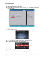
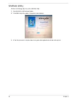
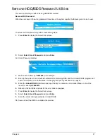
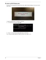
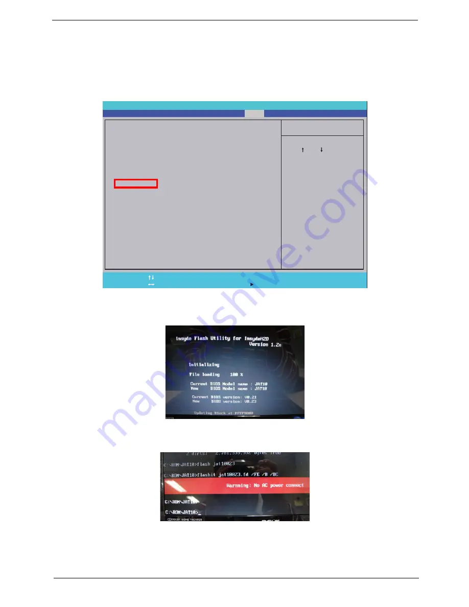
Perform the following steps to use the DOS Flash Utility:
1.
Press F2 during boot to enter the Setup Menu.
2.
Select
Boot Menu
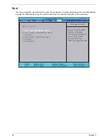
to modify the boot priority order, for example, if using USB HDD to Update BIOS, move
USB HDD to position 1.
3.
Execute the
FLASH.BAT
batch file to update BIOS.
The flash process begins as shown.
4.
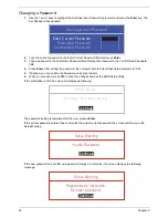
In flash BIOS, the message
Please do not remove AC Power Source
displays.
NOTE:
If the AC power is not connected, the following message displays.
Plug in the AC power to continue.
5.
Flash is complete when the message Flash programming complete displays.
I t e m S p e c i f i c H e l p
U s e < > o r < > t o s e l e c t
a d e v i c e , t h e n p r e s s
< F 5 > t o m o v e i t d o w n t h e
l i s t , o r < F 6 > t o m o v e
i t u p t h e l i s t . P r e s s
< E s c > t o e s c a p e t h e m e n u
F 1
E S C
H e l p
E x i t
S e l e c t I t e m
S e l e c t M e n u
C h a n g e Va l u e s
S e l e c t
S u b M e n u
E n t e r
F 9
F 10
S e t u p D e f a u l t
S a v e a n d E x i t
B o o t p r i o r i t y o r d e r :
1 . I D E 0 : W D C W D 2 5 0 0 B E V T - 2 2 Z C T 0
2 . I D E 1 : T S S T c o r p C D D V D W T S - U 6 3 3 A
3 . U S B F D D :
4 . N e t w o r k B o o t : R e a l t e k B o o t A g e n t
5 . U S B H D D :
6 . U S B C D R O M :
B o o t p r i o r i t y o r d e r :
1 . I D E 0 : W D C W D 2 5 0 0 B E V T - 2 2 Z C T 0
2 . I D E 1 : T S S T c o r p C D D V D W T S - U 6 3 3 A
3 . U S B F D D :
4 . N e t w o r k B o o t : R e a l t e k B o o t A g e n t
5 . U S B H D D :
6 . U S B C D R O M :
F 5 / F 6
I n s y d e H 2 0 S e t u p U t i l i t y R e v . 3 . 5
Information
Advanced
Main
Boot
Exit
Security
Power
Summary of Contents for Aspire 5534 Series
Page 6: ...VI ...
Page 10: ...X Table of Contents ...
Page 32: ...22 Chapter 1 ...
Page 51: ...Chapter 2 41 ...
Page 52: ...42 Chapter 2 ...
Page 65: ...Chapter 3 55 ...
Page 79: ...Chapter 3 69 ...
Page 81: ...Chapter 3 71 5 Lift the Power Board from the Lower Cover ...
Page 83: ...Chapter 3 73 6 Lift the right side speaker out from the Lower Cover as shown ...
Page 89: ...Chapter 3 79 7 Disconnect the I O Board Cable from the I O Board ...
Page 97: ...Chapter 3 87 ...
Page 103: ...Chapter 3 93 ...
Page 107: ...Chapter 3 97 6 Disconnect the LCD cable as shown and remove the cable from the LCD Panel ...
Page 110: ...100 Chapter 3 ...
Page 197: ...Chapter 6 187 ...
Page 224: ...214 ...


