Chapter 3
139
3.
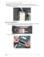
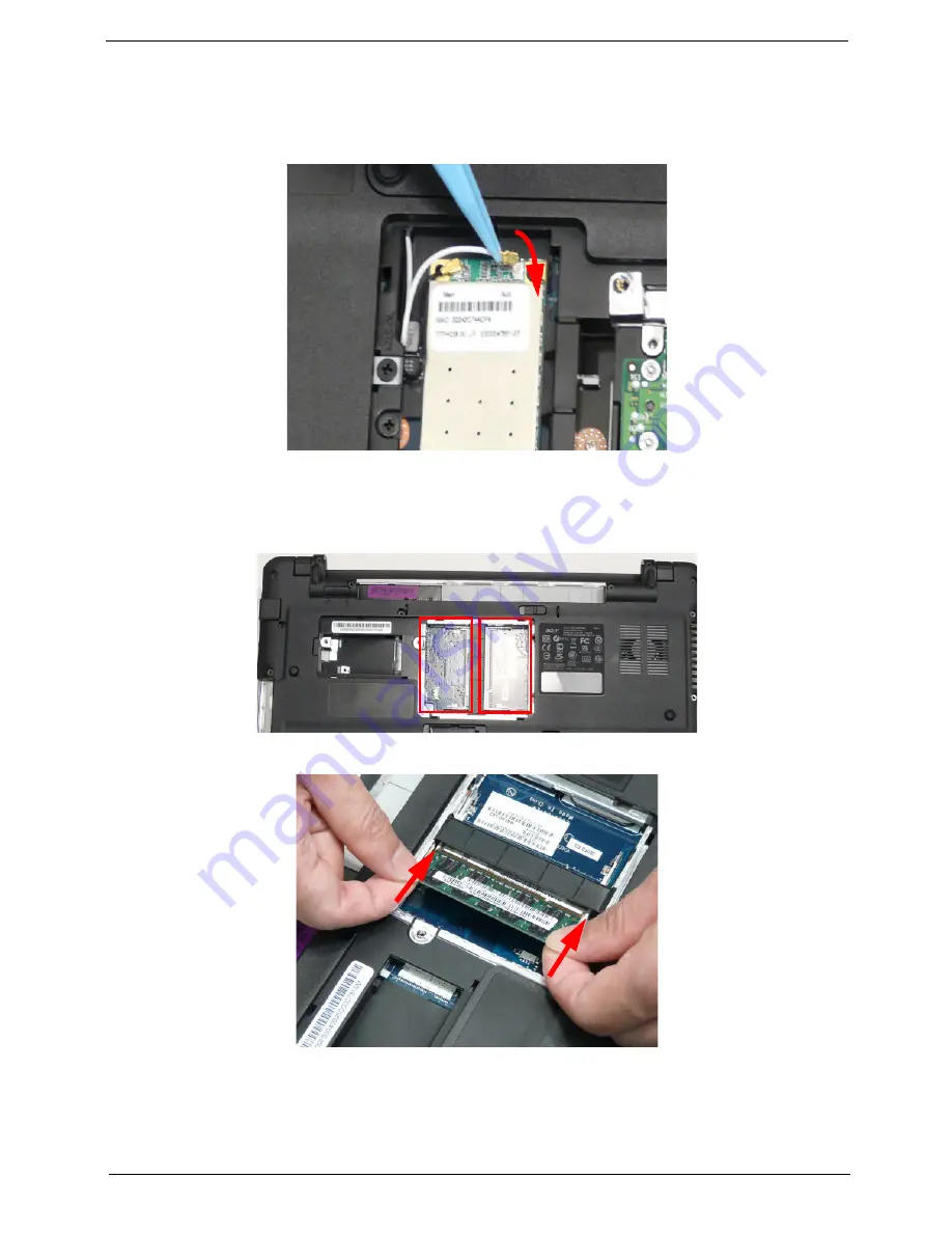
Connect the Antenna cables to the WLAN Board.
NOTE:
Cable placement is White to the AUX terminal (right) and Black to the MAIN terminal (left).
IMPORTANT:
Ensure that the cables are tucked into the chassis to prevent them from being pinched when the
lower covers are replaced.
Replacing the DIMM Modules
1.
Identify the SODIMM to replace. The image below shows the locations of SODIMM slot 0 and SODIMM
slot 1. Slot 0 must be populated first when installing or replacing defective memory.
2.
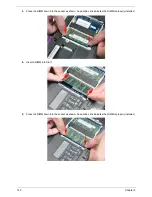
Insert a DIMM into Slot 0.
0
1
Summary of Contents for Aspire 5534 Series
Page 6: ...VI ...
Page 10: ...X Table of Contents ...
Page 32: ...22 Chapter 1 ...
Page 51: ...Chapter 2 41 ...
Page 52: ...42 Chapter 2 ...
Page 65: ...Chapter 3 55 ...
Page 79: ...Chapter 3 69 ...
Page 81: ...Chapter 3 71 5 Lift the Power Board from the Lower Cover ...
Page 83: ...Chapter 3 73 6 Lift the right side speaker out from the Lower Cover as shown ...
Page 89: ...Chapter 3 79 7 Disconnect the I O Board Cable from the I O Board ...
Page 97: ...Chapter 3 87 ...
Page 103: ...Chapter 3 93 ...
Page 107: ...Chapter 3 97 6 Disconnect the LCD cable as shown and remove the cable from the LCD Panel ...
Page 110: ...100 Chapter 3 ...
Page 197: ...Chapter 6 187 ...
Page 224: ...214 ...

