


44
Chapter 3
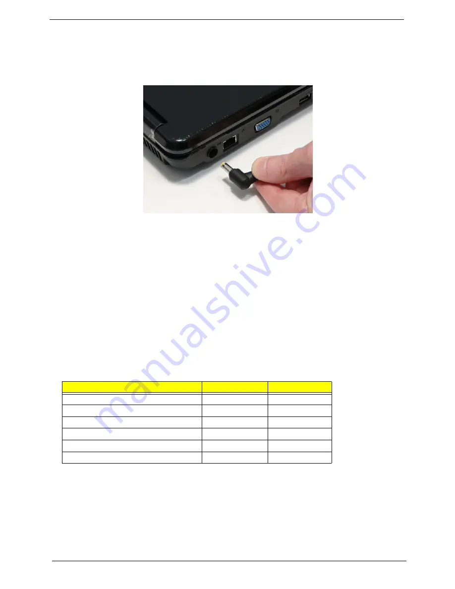
Pre-disassembly Instructions
Before proceeding with the disassembly procedure, make sure that you do the following:
1.
Turn off the power to the system and all peripherals.
2.
Unplug the AC adapter and all power and signal cables from the system.
3.
Place the system on a flat, stable surface.
4.
Remove the battery pack.
Disassembly Process
IMPORTANT:
The LCD Module cannot be disassembled outside of factory conditions. If any part of the LCD
Module is faulty, such as the camera, antenna or LCD panel, the whole module must be replaced.
The disassembly process is divided into the following stages:
•
External module disassembly
•
Main unit disassembly
•
LCD module disassembly
The flowcharts provided in the succeeding disassembly sections illustrate the entire disassembly sequence.
Observe the order of the sequence to avoid damage to any of the hardware components. For example, if you
want to remove the mainboard, you must first remove the keyboard, then disassemble the inside assembly
frame in that order.
Main Screw List
Screw
Quantity
Part Number
SCREW M2.48D 4.0L K 5.5D 0.8T ZKNL
1
86.NAF02.001
SCREW M2.48D 6.0L K 5.5D 0.8T ZKNL
6
86.NAF02.002
SCREW M2.45D 8.0L K 5.5D 0.8T ZKNL
30
86.NAF02.003
SCREW M1.98D 3.0L K 4.6D 0.8T ZKNL
4
86.NAF02.004
SCREW M M 3.0D 3.0L K 4.9D NI +
4
86.NAF02.005
SCREW M M 2.5D 3.2L K 6D NI +
17
86.NAF02.006
Summary of Contents for Aspire 5334
Page 6: ...VI ...
Page 10: ...X Table of Contents ...
Page 15: ...Chapter 1 5 System Block Diagram ...
Page 52: ...42 Chapter 2 ...
Page 74: ...64 Chapter 3 14 Lift the LCD Module clear of the Upper Cover ...
Page 81: ...Chapter 3 71 5 Lift the Speaker clear of the Upper Cover left side first as shown ...
Page 87: ...Chapter 3 77 4 Using both hands lift the Thermal Module clear of the Mainboard ...
Page 102: ...92 Chapter 3 9 The Antennas and cables appear as shown when correctly installed ...
Page 107: ...Chapter 3 97 2 Replace the four 4 screws and screw caps provided ...
Page 112: ...102 Chapter 3 5 Replace the FFC and press down as indicated to secure it to the Upper Cover ...
Page 114: ...104 Chapter 3 2 Replace the two 2 screws to secure the board to the Upper Cover ...
Page 128: ...118 Chapter 3 ...
Page 132: ...122 Chapter 3 ...
Page 159: ...Chapter 5 149 Clear CMOS Jumper Item Description J1 Clear CMOS Jumper J1 ...
Page 244: ...234 Appendix C ...
Page 248: ...238 ...


