


26
Chapter 2
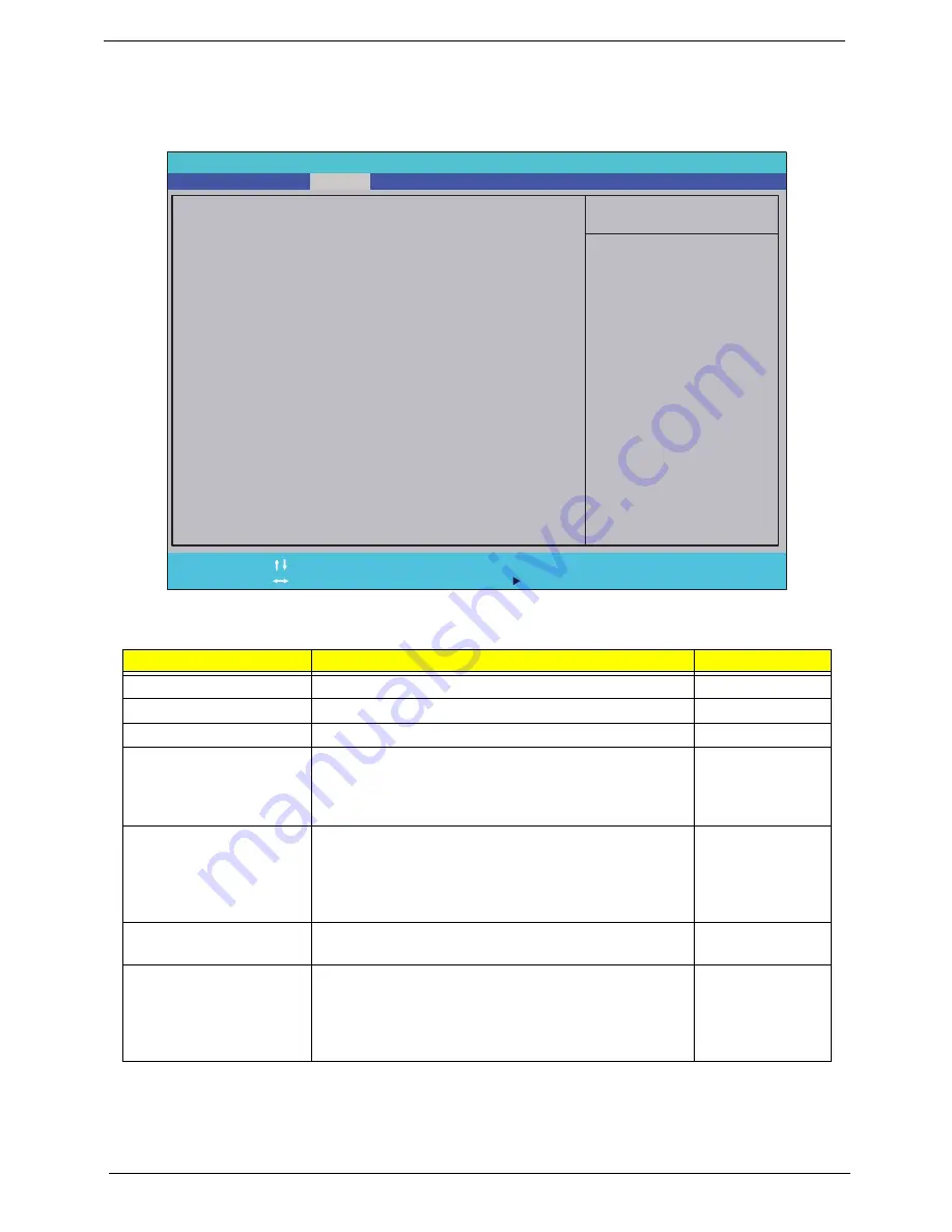
Security
The Security screen contains parameters that help safeguard and protect your computer from unauthorized
use.
The table below describes the parameters in this screen. Settings in
boldface
are the default and suggested
parameter settings.
NOTE:
When you are prompted to enter a password, you have three tries before the system halts. Don’t forget
your password. If you forget your password, you may have to return your notebook computer to your
dealer to reset it.
Parameter
Description
Option
Supervisor Password Is
Shows the setting of the Supervisor password
Clear
or Set
User Password Is
Shows the setting of the user password.
Clear
or Set
HDD Password Is
Shows the setting of the hard disk password.
Clear
or Set
Set Supervisor Password
Press Enter to set the supervisor password. When set,
this password protects the BIOS Setup Utility from
unauthorized access. The user can not either enter the
Setup menu nor change the value of parameters.
N/A
Set User Password
Press Enter to set the user password. When user
password is set, this password protects the BIOS Setup
Utility from unauthorized access. The user can enter
Setup menu only and does not have right to change the
value of parameters.
N/A
Set SATA Port0 HDD
Password
Enter HDD Password.
N/A
Password on Boot
Defines whether a password is required or not while the
events defined in this group happened. The following
sub-options are all requires the Supervisor password
for changes and should be grayed out if the user
password was used to enter setup.
Disabled
or
Enabled
I t e m S p e c i f i c H e l p
I n s t a l l o r C h a n g e t h e
p a s s w o r d a n d t h e l e n g t h
o f p a s s w o r d m u s t b e l e s s
t h a n e i g h t w o r d s .
F 1
E S C
H e l p
E x i t
S e l e c t I t e m
S e l e c t M e n u
C h a n g e Va l u e s
S e l e c t
S u b M e n u
E n t e r
F 9
F 1 0
S e t u p D e f a u l t
S a v e a n d E x i t
C l e a r
C l e a r
C l e a r
[ D i s a b l e d ]
C l e a r
C l e a r
C l e a r
[ D i s a b l e d ]
S u p e r v i s o r P a s s w o r d I s :
U s e r P a s s w o r d I s :
S A T A P o r t 0 D i s k S t a t u s :
S e t S u p e r v i s o r P a s s w o r d
S e t U s e r P a s s w o r d
S e t S A T A P o r t 0 H D D P a s s w o r d
P a s s w o r d o n B o o t
S u p e r v i s o r P a s s w o r d I s :
U s e r P a s s w o r d I s :
S A T A P o r t 0 D i s k S t a t u s :
S e t S u p e r v i s o r P a s s w o r d
S e t U s e r P a s s w o r d
S e t S A T A P o r t 0 H D D P a s s w o r d
P a s s w o r d o n B o o t
F 5 / F 6
I n s y d e H 2 0 S e t u p U t i l i t y R e v . 3 . 5
Information
Main
Boot
Exit
Security
Summary of Contents for Aspire 5334
Page 6: ...VI ...
Page 10: ...X Table of Contents ...
Page 15: ...Chapter 1 5 System Block Diagram ...
Page 52: ...42 Chapter 2 ...
Page 74: ...64 Chapter 3 14 Lift the LCD Module clear of the Upper Cover ...
Page 81: ...Chapter 3 71 5 Lift the Speaker clear of the Upper Cover left side first as shown ...
Page 87: ...Chapter 3 77 4 Using both hands lift the Thermal Module clear of the Mainboard ...
Page 102: ...92 Chapter 3 9 The Antennas and cables appear as shown when correctly installed ...
Page 107: ...Chapter 3 97 2 Replace the four 4 screws and screw caps provided ...
Page 112: ...102 Chapter 3 5 Replace the FFC and press down as indicated to secure it to the Upper Cover ...
Page 114: ...104 Chapter 3 2 Replace the two 2 screws to secure the board to the Upper Cover ...
Page 128: ...118 Chapter 3 ...
Page 132: ...122 Chapter 3 ...
Page 159: ...Chapter 5 149 Clear CMOS Jumper Item Description J1 Clear CMOS Jumper J1 ...
Page 244: ...234 Appendix C ...
Page 248: ...238 ...


