


Chapter 3
65
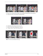
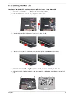
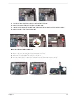
9.
Pull the RF cable through the opening in the lower case as shown.
10. Remove the screw holding the RF board to the lower case.
11. Take out the RF board from the lower case, then detach the RF cable from the RF board as shown.
12. Remove the RJ-11 jack from the lower case.
NOTE: RF board on selected models only.
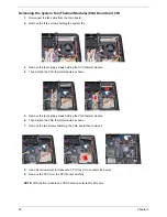
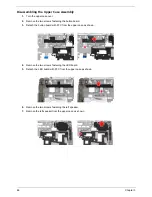
13. Remove the screw fastening the main board to the lower case.
14. Detach the main board from the lower case as shown.
15. Turn the main board over, then remove the DC-in connector from the board as shown.
Summary of Contents for Aspire 5320
Page 6: ...VI ...
Page 10: ...4 Chapter 1 System Block Diagram ...
Page 29: ...Chapter 1 23 ...
Page 44: ...38 Chapter 1 ...
Page 58: ...52 Chapter 2 ...
Page 68: ...62 Chapter 3 10 Detach the LCD module from the main unit ...
Page 74: ...68 Chapter 3 ...
Page 76: ...70 Chapter 3 ...
Page 108: ...102 Chapter 6 ...