background image

Chapter 1

21

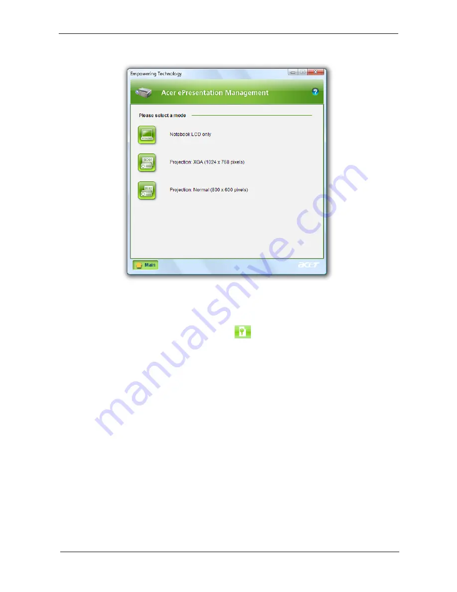
connected to the system. For projectors and external devices that are not auto-detected, launch Acer 
ePresentation Management to choose an appropriate display setting.

NOTE: If the restored resolution is not correct after disconnecting a projector, or you need to use an external 

resolution that is not supported by Acer ePresentation Management, adjust your display settings using 
Display Properties or the utility provided by the graphics vendor.

Acer eDataSecurity Management 

(for selected models)

Acer eDataSecurity Management is an encryption utility that protects your files from being accessed by 
unauthorized persons. It is conveniently integrated with Windows Explorer as a shell extension for quick data 
encryption/decryption and also supports on-the-fly file encryption for Lotus Notes and Microsoft Outlook.

Summary of Contents for Aspire 2420

Page 1: ...Aspire 2920 2920Z 2420 Series Service Guide PRINTED IN TAIWAN Service guide files and updates are available on the ACER CSD web for more information please refer to http csd acer com tw ...

Page 2: ...II Revision History Please refer to the table below for the updates made on Aspire 2920 2920Z 2420 Series service guide Date Chapter Updates ...

Page 3: ...pect to the contents hereof and specifically disclaims any warranties of merchantability or fitness for any particular purpose Any Acer Incorporated software described in this manual is sold or licensed as is Should the programs prove defective following their purchase the buyer and not Acer Incorporated its distributor or its dealer assumes the entire cost of all necessary servicing repair and an...

Page 4: ... bits and pieces of additional information related to the current topic WARNING Alerts you to any damage that might result from doing or not doing specific actions CAUTION Gives precautionary measures to avoid possible hardware or software problems IMPORTANT Reminds you to do specific actions relevant to the accomplishment of procedures ...

Page 5: ... NOT be covered in this generic service guide In such cases please contact your regional offices or the responsible personnel channel to provide you with further technical details 2 Please note WHEN ORDERING FRU PARTS that you should check the most up to date information available on your regional web or channel If for whatever reason a part number change is made it will not be noted in the printe...

Page 6: ...VI ...

Page 7: ...urity Management for selected models 21 Acer eLock Management 22 Acer eRecovery Management 23 Acer eSettings Management 24 Windows Mobility Center 25 Using the System Utilities 26 Acer GridVista dual display compatible 26 Launch Manager 27 Norton Internet Security 27 Hardware Specifications and Configurations 29 System Utilities 39 BIOS Setup Utility 39 Navigating the BIOS Utility 40 Information 4...

Page 8: ...bly Flowchart 86 Removing the LCD Bezel 87 Removing the LCD module with the Brackets 88 Removing the Inverter Board and FPC Cable 90 Removing the LCD Brackets 92 Removing the Antennas 93 Removing the Internal Microphone and Web Camera 94 Troubleshooting 97 System Check Procedures 98 External Diskette Drive Check 98 External CD ROM Drive Check 98 Keyboard or Auxiliary Input Device Check 98 Memory c...

Page 9: ...IX Table of Contents Model Definition and Configuration 130 Test Compatible Components 153 Microsoft Windows Vista Environment Test 154 Online Support Information 157 Index 159 ...

Page 10: ...X Table of Contents ...

Page 11: ...b g Wi Fi CERTIFIED solution supporting Acer SignalUp wireless technology For Aspire 2420 K Intel Celeron mobile processor 530 540 550 1 MB L2 cache 1 73 1 86 2 GHz 533 MHz FSB supporting Intel 64 architecture K Mobile Intel GL960 Express Chipset K Acer InviLink 802 11b g Wi Fi CERTIFIED solution supporting Acer SignalUp wireless technology System Memory K Dual Channel DDR2 SDRAM support K Up to 2...

Page 12: ... stereo speakers K Dolby Home Theater audio enhancement featuring Dolby Digital Dolby Digital Live Dolby Pro Logic II Dolby Digital Stereo Creator Dolby Headphone and Dolby Virtual Speaker technologies K Intel High Definition Audio support K MS Sound compatible K Acer PureZone technology with two built in stereo microphones featuring beam forming echo cancellation and noise suppression technologie...

Page 13: ... display VGA port K S video TV out NTSC PAL port K Headphone speaker line out jack K Microphone in jack K Ethernet RJ 45 port K Modem RJ 11 port K DC in jack for AC adapter Environment K Temperature jOperating 5 C to 35 C jNon operating 20 C to 65 C K Humidity non condensing jOperating 20 to 80 jNon operating 20 to 80 ...

Page 14: ... ETHERNET 10 100 1000MbE 10 USB 2 0 1 1 ports High Definition Audio 1 PATA 66 100 ACPI 1 1 Matrix Storage Technology DO PCI PCI BRIDGE 21 24 C Link0 DEBUG CONN LPC 36 3 SATA LPC I F MDC Card APA2031 OP AMP AZALIA MODEM G1412 25 INT SPKR Line Out No SPDIF RJ11 71 8 0 5 3 ICH M C U SLA Q B 71 GL960 00U SLA5V SATA G792 20 533 667MHz 23 23 TXFM RJ45 Active Managemnet Technology DO Serial Peripheral I ...

Page 15: ...ing key Lanuch Acer Empowering Technology 4 Status indicators Light Emitting Diodes LEDs that light up to show the status of the computer s functions and components 5 Keyboard For entering data into your computer 6 Palmrest Comfortable support area for your hands when you use the computer 7 Touchpad Touch sensitive pointing device which functions like a computer mouse 8 Click buttons left and righ...

Page 16: ...2 Headphones speaker line out jack Connects to audio line out devices e g speakers headphones 3 Unlimited volume control wheel Adjust the volume of the audio out 4 Speakers Left and right speakers deliver stereo audio output Icon Item Description 1 DC in jack Connects to an AC adapter 2 External display VGA port Connects to a display device e g external monitor LCD projector 3 S video TV out NTSC ...

Page 17: ...puter is turned off 5 USB 2 0 port Connect to USB 2 0 devices e g USB mouse USB camera 6 Ethernet RJ 45 port Connects to an Ethernet 10 100 based network 7 Modem RJ 11 port Connects to a phone line 8 5 in 1 card reader Accepts Secure Digital SD MultiMediaCard MMC Memory Stick MS Memory Stick PRO MS PRO xD Picture Card xD Icon Item Description 1 Kensington lock slot Connects to a Kensington compati...

Page 18: ...battery for removal 3 Battery lock Locks the battery in position 4 Memory compartment Houses the computer s main memory 5 Hard disk bay Houses the computer s hard disk secured with screws 6 Ventilation slots and cooling fan Enable the computer to stay cool even after prolonged use Note Do not cover or obstruct the opening of the fan ...

Page 19: ...uttons are called easy launch buttons They are WLAN Internet email Bluetooth Arcade and Acer Empowering Technology The mail and Web browser buttons are pre set to email and Internet programs but can be reset by users To set the Web browser mail and programmable buttons run the Acer Launch Manager Icon Function Description Power Indicates the computer s power status Battery Indicates the computer s...

Page 20: ...he touchpad is the same as clicking the left button Icon Function Description Empowering Technology Launch Acer Empowering Technology user programmable Acer Arcade Launch Acer Arcade utility Wireless communication button indicator Enables disables the wireless function Indicates the status of wireless LAN communication Web browser Internet browser user Programmable Mail Email application user Prog...

Page 21: ...ad s responsiveness Function Left Button 1 Right Button 3 Main touchpad 2 Execute Quickly click twice Tap twice at the same speed as double clicking a mouse button Select Click once Tap once Drag Click and hold then use finger on the touchpad to drag the cursor Tap twice at the same speed as double clicking a mouse button rest your finger on the touchpad on the second tap and drag the cursor Acces...

Page 22: ...percase Num Lock Fn F11 When Num Lock is on the embedded keypad is in numeric mode The keys function as a calculator complete with the arithmetic operators and Use this mode when you need to do a lot of numeric data entry A better solution would be to connect an external keypad Scroll Lock Fn F12 When Scroll Lock is on the screen moves one line up or down when you press the up or down arrow keys r...

Page 23: ...rk domain M Minimizes all windows R Open the Run dialog box T Cycle through programs on the taskbar U Open Ease of Access Center X Open Windows Mobility Center BREAK Display the System Properties dialog box SHIFT M Restore minimized windows to the desktop TAB Cycle through programs on the taskbar by using Windows Flip 3 D SPACEBAR Bring all gadgets to the front and select Windows Sidebar CTRL F Se...

Page 24: ...ement Launches Acer ePower Management in Acer Empowering Technology Fn F4 Sleep Puts the computer in Sleep mode Fn F5 Display toggle Switches display output between the display screen external monitor if connected and both Fn F6 Screen blank Turns the display screen backlight off to save power Press any key to return Fn F7 Touchpad toggle Turns the internal touchpad on and off Fn F8 Speaker toggle...

Page 25: ...lt Gr and then press the 5 key at the upper center of the keyboard NOTE Note Some fonts and software do not support the Euro symbol Please refer to www microsoft com typography faq faq12 htm for more information The US dollar sign 1 Open a text editor or word processor 2 Hold Shift and then press the 4 key at the upper center of the keyboard NOTE This function varies by the operating system versio...

Page 26: ...l function Empowering Technology password Before using Acer eLock Management and Acer eRecovery Management you must initialize the Empowering Technology password Right click on the Empowering Technology toolbar and select Password Setup to do so If you have not initialized the Empowering Technology password and run Acer eLock Management or Acer eRecovery Management you will be asked to create it N...

Page 27: ...h to the appropriate profile when you move from one location to another Settings stored include network connection settings IP and DNS settings wireless AP details etc as well as default printer settings Security and safety concerns mean that Acer eNet Management does not store username and password information ...

Page 28: ...You can also create customized power plans You can create switch between edit delete and restore power plans as described below View and adjust settings for On Battery and Plugged In modes by clicking the appropriate tabs You can open Windows power options by clicking More Power Options NOTE You cannot delete the predefined power plans To create a new power plan Creating customized power plans all...

Page 29: ...ou wish to edit 2 Adjust settings as required 3 Click Apply to save your new settings To delete a power plan You cannot delete the power plan you are currently using If you want to delete the active power plan switch to another one first 1 Select the power plan you wish to delete from the drop down list 2 Click the Delete Power Plan icon Battery status For real time battery life estimates based on...

Page 30: ... 2 speakers via Dolby Virtual Speaker technology Music mode lets you enjoy your favorite tunes in vivid detail Acer ePresentation Management Acer ePresentation Management lets you project your computer s display to an external display device or projector using the hotkey Fn F5 If auto detection hardware is implemented in the system and the external display supports it your system display will be a...

Page 31: ... supported by Acer ePresentation Management adjust your display settings using Display Properties or the utility provided by the graphics vendor Acer eDataSecurity Management for selected models Acer eDataSecurity Management is an encryption utility that protects your files from being accessed by unauthorized persons It is conveniently integrated with Windows Explorer as a shell extension for quic...

Page 32: ... no way to decrypt your encrypted file Be sure to safeguard all related passwords Acer eLock Management Acer eLock Management is simple yet effective utility that allows you to lock removable storage optical and floppy drive devices to ensure that data can t be stolen while your system is unattended K Removable Storage Devices includes USB disk drives USB pen drives USB flash drives USB MP3 drives...

Page 33: ...ement is a versatile backup utility It allows you to create full or incremental backups burn the factory default image to optical disc and restore from previously created backups or reinstall applications and drivers By default user created backups are stored to the D drive Acer eRecovery Management provides you with K Password protection Empowering Technology password K Full and incremental backu...

Page 34: ...ing your system using a CD or Acer eRecovery Management detach all peripherals except the external Acer ODD if your computer has one including your Acer ezDock Acer eSettings Management Acer eSettings Management allows you to inspect hardware specifications set BIOS passwords and modify boot options Acer eSettings Management also K Provides a simple graphical user interface for navigation K Prints...

Page 35: ... power plan volume wireless networking on off external display settings display orientation and synchronization status Windows Mobility Center also includes Acer specific settings like Bluetooth Add Device if applicable sharing folders overview sharing service on or off and a shortcut to the Acer user guide drivers and utilities To launch Windows Mobility Center K Use the shortcut key X K Start Wi...

Page 36: ...e windows on the same screen To access this function please go to Start All Programs and click on Acer GridVista You may choose any one of the four display settings indicated below Double verticle Triple primary at left Triple primary at right or Quad Acer Gridvista is dual display compatible allowing two displays to be partitioned indepently Acer Gridvista is dual display compatible allowing two ...

Page 37: ...ttons located above the keyboard You can access the Launch Manager by clicking on Start All Programs Launch Manager to start the application Norton Internet Security Norton Internet Security is an anti virus utility that can protect against viruses keeping your data safe and secure How do I check for viruses 1 Double click the Norton Internet Security icon on the Windows desktop 2 Select Tasks Sca...

Page 38: ...n when scanning your computer for the first time You can schedule customized virus scans that run unattended on specific dates and times or at periodic intervals If you are using the computer when the scheduled scan begins it runs in the background so that you do not have to stop working For more information refer to the Norton Internet Security help files ...

Page 39: ... degree C Fan Speed rpm Acoustic Level dBA 45 50 0 3000 29 55 66 0 3300 33 68 74 3300 3800 38 78 83 3800 4100 40 86 91 4100 4800 40 BIOS Item Specification BIOS vendor Phoenix BIOS Version 1 02 MP version BIOS ROM type SST AMD 1MB CMOS Boot Block Flash Memory BIOS ROM size 1M byte FLASH ROM SST BIOS package 10 lead TSOP 10mmx20mm Supported protocols ACPI 1 0b 2 0 3 0 compliance PCI 2 2 System HDD ...

Page 40: ...MHz Supports DIMM voltage 1 8V and 0 9V Supports DIMM package 200 pin soDIMM Memory module combinations You can install memory modules in any combinations as long as they match the above specifications Memory Combinations Slot 1 Slot 2 Total Memory 0MB 256MB 256MB 0MB 512MB 512MB 0MB 1024MB 1024MB 0MB 2048MB 2048MB 256MB 256MB 512MB 256MB 512MB 768MB 256MB 1024MB 1280MB 256MB 2048MB 2304MB 512MB 2...

Page 41: ...orting Acer SignalUp with InviLink Nplify wireless technology Intel PRO Wireless 3945ABG dual band tri mode 802 11a b g Wi Fi CERTIFIED network connection supporting Acer SignalUp wireless technology Data throughput 11 54 Mbps up to 270 Mbps for Draft N Protocol 802 11b g Draft N Interface PCI bus mini PCI socket for wireless module Hard Disk Drive Interface Item Vendor Model Name HGST 2 5 HTS5425...

Page 42: ...mory 2MB Interface PATA Applicable disc format 1 Reads and writes data in each CD ROM CD ROMXA CD I FMV Video CD and CD EXTRA 2 Reads data in Photo CD Single and multi session 3 Reads and writes standard CD DA 4 Reads and writes CD R discs conforming to Orange Book Part 2 5 Reads and writes CD RW discs conforming to Orange Book Part 3 6 Reads data in DVD ROM Applicable DVD formats Read DVD DVD ROM...

Page 43: ...D text DVD DVD VIDEO DVD ROM DVD R 3 9GB 4 7GB DVD R DL DVD RW DVD RAM DVD R DVD R DL DVD RW CD CD DA Red Book Standard Audio CD CD TEXT CD ROM Yellow Book Mode1 2 Standard Data CD ROM XA Mode2 Form1 2 Photo CD Multi Session CD I Green Book Mode2 Form1 2 Ready Bridge CD Extra CD Plus Blue Book Audio Text Video Video CD White Book MPEG1 Video CD R Orange Book Part CD RW HSRW Orange Book Part Volume...

Page 44: ... Internal speaker Quantity Yes 2 1 5W speakers Video Memory Item Specification Chipset UMA Memory size 8 MB Item Specification Chipset ICH8M USB Compliancy Level 2 0 OHCI USB 1 1 and USB 2 0 Host controller Number of USB port 4 Location Two on the left side one on the right side Serial port function control Enable Disable by BIOS Setup PCMCIA Port Item Specification PCMCIA controller ENE CB714 141...

Page 45: ...y Yes Internal external keyboard work simultaneously Plug USB keyboard to the USB port directly Yes Battery Item Specification Vendor model name SANYO 6cell 2 0 SIMPLO 6cell 2 0 Sanyo 6cell 2 4 SONY 6cell 2 4 Battery Type Li ion Pack capacity 2 0 AH SANYO 6cell 2 0 2 0 AH SIMPLO 6cell 2 0 2 4 AH Sanyo 6cell 2 4 2 4 AH SIMPLO 6cell 2 4 Number of battery cell 6 Package configuration 3 cells in serie...

Page 46: ...290 max Physical Size mm 275 82 x 178 x 5 5 max 275 82 x 178 x 5 5 max Electrical Interface 1 channel LVDS 1 channel LVDS Support Color 262 144 262 144 Viewing Angle degree Horizontal Right Left Vertial Upper Lower 45 45 15 35 45 45 15 35 Temperature Range C Operating Storage shipping 0 to 50 40 to 60 0 to 50 40 to 60 LCD Inverter Item Specification Vendor model name YEC YNV W05 Brightness conditi...

Page 47: ...urned off completely Working G0 S0 Individual devices such as the CPU and hard disc may be power managed in this state Suspend to RAM S3 CPU set power down VGA Suspend PCMCIA Suspend Audio Power Down Hard Disk Power Down CD ROM Power Down Super I O Low Power mode Save to Disk S4 Also called Hibernation Mode System saves all system states and data onto the disc prior to power off the whole system ...

Page 48: ...38 Chapter 1 ...

Page 49: ...ce without entering BIOS Setup Utility please set the parameter to enabled Press F12 during POST to enter multi boot menu In this menu user can change boot device without entering BIOS SETUP Utility Phoenix TrustedCore tm Setup Utility Main CPU Type CPU Speed IDE0 Model Name IDE0 Serial Number ATAPI Model Name System BIOS Version VGA BIOS Version KBC Version Serial Number Asset Tag Number Product ...

Page 50: ...em K Press Esc while you are in any of the menu options to go to the Exit menu K In any menu you can load default settings by pressing F9 You can also press F10 to save any changes made and exit the BIOS Setup Utility NOTE You can change the value of a parameter if it is enclosed in square brackets Navigation keys for a particular menu are shown on the bottom of the screen Help for parameters are ...

Page 51: ...Asset Tag Number This field displays the asset tag number of the system Product Name This field shows product name of the system Manufacturer Name This field displays the manufacturer of this system UUID Number Universally Unique Identifier UUID is an identifier standard used in software construction standardized by the Open Software Foundation OSF as part of the Distributed Computing Environment ...

Page 52: ...tm Setup Utility Main Item Specific Help Tab Shift Tab or Enter selects field System Time System Date System Memory Extended Memory Video Memory Quiet Boot Network Boot F12 Boot Menu D2D Recovery SATA Mode F1 Esc Help Exit Select Item Select Menu Change Values Select Sub Menu Enter F9 F10 Setup Defaults Save and Exit Information Security Boot Exit 10 10 10 26 2007 640 KB 1014 MB 8 MB Enabled Enabl...

Page 53: ...e extended memory in the system Extended Memory size Total memory size 1MB VGA Memory Shows the VGA memory size VGA Memory size 128 256 MB Quiet Boot Determines if Customer Logo will be displayed or not shows Summary Screen is disabled or enabled Enabled Customer Logo is displayed and Summary Screen is disabled Disabled Customer Logo is not displayed and Summary Screen is enabled Option Enabled or...

Page 54: ...ity Main Item Specific Help Supervisor Password controls access of the whole setup utility It can be used to boot up when Password on boot is enabled Supervisor Password Is User Password Is Set User Password Password Password on Boot HDD Password Is Set HDD Set Supervisor Password F1 Esc Help Exit Select Item Select Menu Change Values Select Sub Menu Enter F9 F10 Setup Defaults Save and Exit Infor...

Page 55: ...ired you can opt to enable the Password on boot parameter 5 When you are done press u to save the changes and exit the BIOS Setup Utility Parameter Description Option Supervisor Password Is Shows the setting of the Supervisor password Clear or Set User Password Is Shows the setting of the user password Clear or Set HDD Password Is Shows the setting of the hard disk password Clear or Set Set Superv...

Page 56: ...e BIOS Setup Utility Changing a Password 1 Use the w and y keys to highlight the Set Supervisor Password parameter and press the e key The Set Password box appears 2 Type the current password in the Enter Current Password field and press e 3 Type a password in the Enter New Password field Retype the password in the Confirm New Password field 4 Press e After setting the password the computer sets t...

Page 57: ...current password entered does not match the actual current password the screen will show you the Setup Warning If the new password and confirm new password strings do not match the screen will display the following message ...

Page 58: ...etup Utility Main Item Specific Help Use or to select a device then press F6 to move it up the list or F5 to move it down the list Press Esc to escape the menu Boot priority order F1 Esc Help Exit Select Item Select Menu Change Values Select Sub Menu Enter F9 F10 Setup Defaults Save and Exit Information Security Boot Exit 2 3 4 5 6 7 1 IDE0 XXXXXXXXXXX XX CD DVD XXXXXXXXXXX XXX XX XXXX XX PCI LAN ...

Page 59: ...tup data to CMOS Load Setup Default Load default values for all SETUP item Discard Changes Load previous values from CMOS for all SETUP items Save Changes Save Setup Data to CMOS Phoenix TrustedCore tm Setup Utility Main Item Specific Help Exit System Setup and save your changes to CMOS F1 Esc Help Exit Select Item Select Menu Change Values Select Sub Menu Enter F9 F10 Setup Defaults Save and Exit...

Page 60: ...ery Diskette before you use the Phlash utility NOTE Do not install memory related drivers XMS EMS DPMI when you use the Phlash NOTE Please use the AC adaptor power supply when you run the Phlash utility If the battery pack does not contain enough power to finish BIOS flash you may not boot the system because the BIOS is not completely loaded Fellow the steps below to run the Phlash 1 Prepare a boo...

Page 61: ... Remove HDD Password K If you key in wrong HDD password for three time HDD password error code would display on the screen See the image below K If you need to solve HDD password locked problem you can run unlock6 exe 1 Key in unlock6 03567 00 2 Select 2 3 Choose one upper case string ...

Page 62: ...52 Chapter 2 K Reboot system and key in N9H7W7I 9HNXDDI BCIKFVX TPFIK1K or Q918H7I to HDD user password ...

Page 63: ...K Wrist grounding strap and conductive mat for preventing electrostatic discharge K Flat screwdriver K Philips screwdriver K Hex screwdriver K Plastic flat screwdriver K Plastic tweezers NOTE The screws for the different components vary in size During the disassembly process group the screws with the corresponding components to avoid mismatch when putting back the components Chapter 3 Machine Disa...

Page 64: ...embly LCD module disassembly The flowcharts provided in the succeeding disassembly sections illustrate the entire disassembly sequence Observe the order of the sequence to avoid damage to any of the hardware components For example if you want to remove the main board you must first remove the keyboard then disassemble the inside assembly frame in that order Main Screw List Item Screw Color Part No...

Page 65: ...then disassemble the inside assembly frame in that order Screw List Item Screw Color Part No A M2 x L3 Black 86 00D29 620 B M2 x L4 Black 86 00D68 620 C M3 x L4 Silver 86 9A524 4R0 D M2 x L5 Black 86 00E32 725 EXTERNAL MODULE DISASSEMBLY WLAN BOARD TURN OFF POWER AND PERIPHERALS UNPLUG POWER CABLES Ax2 LOWER COVER Bx4 Captive Screwx5 DIMM MODULES OPTICAL DISK DRIVE MODULE Ax2 OPTICAL DISK DRIVE Cx...

Page 66: ... Slide the battery lock unlock latch to the unlock position 3 Slide and hold the battery release latch to the release position 1 then slide out the battery pack from the main unit 2 Removing the SD dummy card 1 Push the SD dummy card all the way in to eject it 1 2 ...

Page 67: ...ull it out from the slot Removing the ExpressCard dummy card 1 Push the ExpressCard dummy card all the way in to eject it 2 Pull it out from the slot Removing the Lower Cover 1 See Removing the Battery Pack on page 56 ...

Page 68: ...ee Removing the ExpressCard dummy card on page 57 4 Remove the four screws B and loosen the five captive screws on the lower cover 5 Use a plastic screw driver to carefully pry open the lower cover Step Size Quantity Color Torque 1 4 M2 x L12 4 Black 1 6 kgf cm ...

Page 69: ... the DIMM 1 See Removing the Battery Pack on page 56 2 See Removing the SD dummy card on page 56 3 See Removing the ExpressCard dummy card on page 57 4 See Removing the Lower Cover on page 57 5 Push out the latches on both sides of the DIMM socket to release the DIMM ...

Page 70: ...WLAN Board Modules 1 See Removing the Battery Pack on page 56 2 See Removing the SD dummy card on page 56 3 See Removing the ExpressCard dummy card on page 57 4 See Removing the Lower Cover on page 57 5 Disconnect the antenna cables from the WLAN board ...

Page 71: ...OTE When attaching the antenna back to the WLAN board make sure the cable are arranged properly Removing the Hard Disk Drive Module 1 See Removing the Battery Pack on page 56 2 See Removing the SD dummy card on page 56 3 See Removing the ExpressCard dummy card on page 57 4 See Removing the Lower Cover on page 57 Step Size Quantity Color Torque 1 2 M2 x L3 2 Black 1 6 kgf cm ...

Page 72: ...ing the hard disk drive module 6 Slide and lift up the hard disk drive module to remove NOTE To prevent damage to device avoid pressing down on it or placing heavy objects on top of it Step Size Quantity Color Torque 1 M2 x L5 1 Black 1 6 kgf cm ...

Page 73: ... the bracket Removing the Optical Drive Module 1 See Removing the Battery Pack on page 56 2 See Removing the Lower Cover on page 57 3 Carefully use a plastic screw driver to eject the optical drive tray Step Size Quantity Color Torque 1 4 M3 x L4 4 Silver 3 0 kgf cm ...

Page 74: ...optical drive module out from the main unit 5 Remove the two screws A securing the locker bracket and remove the locker bracket from the optical disk drive module Step Size Quantity Color Torque 1 2 M2 x L4 2 Black 1 6 kgf cm ...

Page 75: ...crew Color Part No A M2 x L3 Black 86 00D29 620 D M2 x L5 Black 86 00E32 725 F M2 x L4 Black 86 00F24 724 H M2 5 x L8 Black 86 00E34 738 MAIN UNIT KEYBOARD MAIN BOARD Fx2 MAIN UNIT DISASSEMBLY LCD MODULE H x 2 Ax7 Fx4 UPPER CASE Dx9 LEFT AND RIGHT SPEAKER MODULE MODEM BOARD 2xSCREWS CPU VGA THERMAL MODULE CPU TOUCH PAD BRACKET ASSEMBLY Fx2 TOUCH PAD BRACKET LAUNCH BOARD A x 4 5xCaptive Screws TOUC...

Page 76: ...66 Chapter 3 3 Disconnect the heatsink fan connector from the main board 4 Remove the five screws securing the CPU and VGA heatsink module in place ...

Page 77: ... 3 67 5 Slide out and remove the heatsink module Removing the CPU 1 See Removing the Battery Pack on page 56 2 See Removing the Lower Cover on page 57 3 See Removing the CPU and VGA Heatsink Module on page 65 ...

Page 78: ...Using a flat screwdriver turn the CPU socket latch counter clockwise to release the CPU 5 Lift up carefully to remove the CPU NOTE When installing the CPU make sure to install the CPU with PIN 1 at the corner as shown ...

Page 79: ...er 3 69 Removing the Keyboard 1 See Removing the Battery Pack on page 56 2 Push down on the lock and release the latches securing the keyboard to the upper case 3 Turn over the keyboard on the touchpad area ...

Page 80: ...rd to remove the keyboard Removing the LCD Module 1 See Removing the Battery Pack on page 56 2 See Removing the Lower Cover on page 57 3 See Removing the WLAN Board Modules on page 60 4 See Removing the Keyboard on page 69 5 See Removing the LCD Module on page 70 ...

Page 81: ...on panel of the system and three screws A on the battery bay area 7 Turn over the system and open the LCD panel and gently pry up and remove the middle cover Step Size Quantity Color Torque 1 2 M2 5 x L8 2 Black 3 0 kgf cm 3 5 M2 x L3 3 Black 1 6 kgf cm ...

Page 82: ...72 Chapter 3 8 Carefully pry up the middle cap cover and remove it 9 Release the wireless antennas from the latches 10 Disconnect the LCD cable from the main board ...

Page 83: ...Chapter 3 73 11 Remove the four screws A securing the left and right hinge caps 12 Remove the left and right hinge caps Step Size Quantity Color Torque 1 4 M2 x L3 4 Black 1 6 kgf cm ...

Page 84: ...Battery Pack on page 56 2 See Removing the SD dummy card on page 56 3 See Removing the ExpressCard dummy card on page 57 4 See Removing the Lower Cover on page 57 5 See Removing the DIMM on page 59 6 See Removing the WLAN Board Modules on page 60 7 See Removing the Hard Disk Drive Module on page 61 8 See Removing the Optical Drive Module on page 63 9 See Removing the CPU and VGA Heatsink Module on...

Page 85: ... See Removing the Keyboard on page 69 12 See Removing the LCD Module on page 70 13 Disconnect the Launch board cable from the CN1 on the main board 14 Disconnect the touchpad cable from the TOUCHPAD1 on the main board ...

Page 86: ...76 Chapter 3 15 Remove the nine screws D on the bottom panel 16 Gently raise the upper case from the main unit Step Size Quantity Color Torque 1 9 M2 x L5 9 Black 1 6 kgf cm ...

Page 87: ...emoving the WLAN Board Modules on page 60 7 See Removing the Hard Disk Drive Module on page 61 8 See Removing the Optical Drive Module on page 63 9 See Removing the CPU and VGA Heatsink Module on page 65 10 See Removing the CPU on page 67 11 See Removing the Keyboard on page 69 12 See Removing the LCD Module on page 70 13 See Separating the Upper Case from the Lower Case on page 74 14 Release the ...

Page 88: ... on page 57 4 See Removing the Lower Cover on page 57 5 See Removing the DIMM on page 59 6 See Removing the WLAN Board Modules on page 60 7 See Removing the Hard Disk Drive Module on page 61 8 See Removing the Optical Drive Module on page 63 9 See Removing the CPU and VGA Heatsink Module on page 65 10 See Removing the CPU on page 67 11 See Removing the Keyboard on page 69 12 See Removing the LCD M...

Page 89: ...from the Lower Case on page 74 14 Disconnect the touch pad cable from the touch pad board 15 Carefully pry loose and remove the touch pad board WARNING The touchpad board is glued to the upper case only remove the touchpad board if it is defective ...

Page 90: ...6 See Removing the WLAN Board Modules on page 60 7 See Removing the Hard Disk Drive Module on page 61 8 See Removing the Optical Drive Module on page 63 9 See Removing the CPU and VGA Heatsink Module on page 65 10 See Removing the CPU on page 67 11 See Removing the Keyboard on page 69 12 See Removing the LCD Module on page 70 13 See Separating the Upper Case from the Lower Case on page 74 14 Disco...

Page 91: ...Chapter 3 81 15 Remove the two screws F holding the main board 16 Carefully remove the main board Step Size Quantity Color Torque 1 2 M2 x L4 2 Black 1 6 kgf cm ...

Page 92: ...7 See Removing the Hard Disk Drive Module on page 61 8 See Removing the Optical Drive Module on page 63 9 See Removing the CPU and VGA Heatsink Module on page 65 10 See Removing the CPU on page 67 11 See Removing the Keyboard on page 69 12 See Removing the LCD Module on page 70 13 See Separating the Upper Case from the Lower Case on page 74 14 See Removing the main board on page 80 15 Remove the f...

Page 93: ...ge 57 5 See Removing the DIMM on page 59 6 See Removing the WLAN Board Modules on page 60 7 See Removing the Hard Disk Drive Module on page 61 8 See Removing the Optical Drive Module on page 63 9 See Removing the CPU and VGA Heatsink Module on page 65 10 See Removing the CPU on page 67 11 See Removing the Keyboard on page 69 12 See Removing the LCD Module on page 70 13 See Separating the Upper Cas...

Page 94: ...pter 3 15 Remove the 2 screws securing the modem card 16 Disconnect the cable from the modem board 17 Remove the modem board from the main board Step Size Quantity Color Torque 1 2 M2 x L4 2 Silver 1 8 kgf cm ...

Page 95: ...ge 61 8 See Removing the Optical Drive Module on page 63 9 See Removing the CPU and VGA Heatsink Module on page 65 10 See Removing the CPU on page 67 11 See Removing the Keyboard on page 69 12 See Removing the LCD Module on page 70 13 See Separating the Upper Case from the Lower Case on page 74 14 See Removing the main board on page 80 15 Detach the Bluetooth cable from the main board 16 Carefully...

Page 96: ...olor Part No E M2 5 x L5 Black 86 00F87 735 G M2 x L3 Silver 86 9A552 3R0 I M2 5 x L4 Silver 86 00E41 134 LCD MODULE LCD BEZEL Ex6 LCD ASSEMBLY LEFT LCD BRACKET Gx2 RIGHT LCD BRACKET Gx2 LCD FPC CABLE INVERTER BOARD LCD BACK PANEL ANTENNAS LCD MODULE DISASSEMBLY Ix2 Ix2 VGA CAMERA INTERNAL MICROPHONE ...

Page 97: ... page 57 4 See Removing the Lower Cover on page 57 5 See Removing the WLAN Board Modules on page 60 6 See Removing the Keyboard on page 69 7 See Removing the LCD Module on page 70 8 Remove the four upper and the two lower bezel screw caps 9 Remove the six screws E on the LCD module in the order as shown Step Size Quantity Color Torque 1 6 M2 5 x L5 6 Black 3 0 kgf cm ...

Page 98: ...er 3 10 Carefully pry open the LCD bezel and remove the bezel from the LCD module Removing the LCD module with the Brackets 1 See Removing the Battery Pack on page 56 2 See Removing the SD dummy card on page 56 ...

Page 99: ... Removing the Lower Cover on page 57 5 See Removing the WLAN Board Modules on page 60 6 See Removing the Keyboard on page 69 7 See Removing the LCD Module on page 70 8 See Removing the LCD Bezel on page 87 9 Disconnect the cables from the microphone board and camera board ...

Page 100: ... See Removing the SD dummy card on page 56 3 See Removing the ExpressCard dummy card on page 57 4 See Removing the Lower Cover on page 57 5 See Removing the WLAN Board Modules on page 60 6 See Removing the Keyboard on page 69 7 See Removing the LCD Module on page 70 8 See Removing the LCD Bezel on page 87 9 See Removing the LCD module with the Brackets on page 88 Step Size Quantity Color Torque 1 ...

Page 101: ...the inverter board cable from its connector then disconnect the 2P cable on the inverter board to remove it 11 Detach the acetic tapes holding the FPC cable from the LCD panel and detach the acetic tape securing the FPC connector ...

Page 102: ...e Removing the ExpressCard dummy card on page 57 4 See Removing the Lower Cover on page 57 5 See Removing the WLAN Board Modules on page 60 6 See Removing the Keyboard on page 69 7 See Removing the LCD Module on page 70 8 See Removing the LCD Bezel on page 87 9 See Removing the LCD module with the Brackets on page 88 10 See Removing the Inverter Board and FPC Cable on page 90 ...

Page 103: ...moving the Lower Cover on page 57 5 See Removing the WLAN Board Modules on page 60 6 See Removing the Keyboard on page 69 7 See Removing the LCD Module on page 70 8 See Removing the LCD Bezel on page 87 9 See Removing the LCD module with the Brackets on page 88 10 Release the antenna cables from the aluminium tapes 11 Remove the tapes holding the antenna cables in place and release the cables from...

Page 104: ...r 3 12 Remove the tapes together with the antenna cables from the back cover Removing the Internal Microphone and Web Camera 1 See Removing the Battery Pack on page 56 2 See Removing the SD dummy card on page 56 ...

Page 105: ...d Modules on page 60 6 See Removing the Keyboard on page 69 7 See Removing the LCD Module on page 70 8 See Removing the LCD Bezel on page 87 9 See Removing the LCD module with the Brackets on page 88 10 See Removing the Antennas on page 93 11 Remove the internal microphone from the back cover 12 Remove the Web camera from the back cover ...

Page 106: ...96 Chapter 3 ...

Page 107: ...ch page to go to Symptoms Verified Go To Power failure The power indicator does not go on or stay on Power System Check on page 99 POST does not complete No beep or error codes are indicated Power On Self Test POST Error Message on page 102 Undetermined Problems on page 116 POST detects an error and displayed messages on screen Error Message List on page 103 Other symptoms i e LCD display problems...

Page 108: ...to it The label can cause damage to the drive or can cause the drive to fail Do the following to select the test device 1 Boot from the diagnostics diskette and start the diagnostics program 2 See if CD ROM Test is passed when the program runs to CD ROM Test 3 Follow the instructions in the message window If an error occurs reconnect the connector on the System board If the error still remains 1 R...

Page 109: ...nstructions in the message window NOTE Make sure that the DIMM is fully installed into the connector A loose connection can cause an error Power System Check To verify the symptom of the problem power on the computer using each of the following power sources 1 Remove the battery pack 2 Connect the power adapter and check that power is supplied 3 Disconnect the power adapter and install the charged...

Page 110: ...e following K Replace the System board K If the problem is not corrected see Undetermined Problems on page 116 K If the voltage is not correct go to the next step NOTE An audible noise from the power adapter does not always indicate a defect 3 If the power on indicator does not light up check the power cord of the power adapter for correct continuity and installation 4 If the operational charge do...

Page 111: ... that has less than 50 of the total power remaining when installed in the computer If the battery status indicator does not light up remove the battery pack and let it return to room temperature Re install the battery pack If the charge indicator still does not light up replace the battery pack If the charge indicator still does not light up replace the DC DC charger board Touchpad Check If the to...

Page 112: ...ext possible FRU to be replaced when servicing a computer If the symptom is not listed see Undetermined Problems on page 116 The following lists the error messages that the BIOS displays on the screen and the error symptoms classified by function NOTE Most of the error messages occur during POST Some of them display information about a hardware device e g the amount of memory installed Others may ...

Page 113: ...e Fixed Disk Reconnect hard disk drive connector Load Default Settings in BIOS Setup Utility Hard disk drive System board Stuck Key see Keyboard or Auxiliary Input Device Check on page 98 Keyboard error see Keyboard or Auxiliary Input Device Check on page 98 Keyboard Controller Failed see Keyboard or Auxiliary Input Device Check on page 98 Keyboard locked Unlock key switch Unlock external keyboard...

Page 114: ...he drive is defined with the proper diskette type in BIOS Setup Utility System cache error Cache disabled System board CPU ID System board DMA Test Failed DIMM System board Software NMI Failed DIMM System board Fail Safe Timer NMI Failed DIMM System board Device Address Conflict Run Load Default Settings in BIOS Setup Utility RTC battery System board Allocation Error for device Run Load Default Se...

Page 115: ... source battery pack and power adapter See Power System Check on page 99 Reconnect the LCD connector Hard disk drive LCD inverter ID LCD cable LCD Inverter LCD System board No beep power on indicator turns on and LCD is blank But you can see POST on an external CRT Reconnect the LCD connectors LCD inverter ID LCD cable LCD inverter LCD System board No beep power on indicator turns on and a blinkin...

Page 116: ...tialize keyboard controller 16h 1 2 2 3 BIOS ROM checksum 17h Initialize cache before memory autosize 18h 8254 timer initialization 1Ah 8237 DMA controller initialization 1Ch Reset Programmable Interrupt Controller 20h 1 3 1 1 Test DRAM refresh 22h 1 3 1 3 Test 8742 Keyboard Controller 24h Set ES segment register to 4 GB 26h Enable A20 line 28h Autosize DRAM 29h Initialize POST Memory Manager 2Ah ...

Page 117: ...isplay service 5Ah Display prompt Press F2 to enter SETUP 5Bh Disable CPU cache 5Ch Test RAM between 512 and 640 KB 60h Test extended memory 62h Test extended memory address lines 64h Jump to User Patch1 66h Configure advanced cache registers 67h Initialize Multi Processor APIC 68h Enable external and CPU caches 69h Setup System Management Mode SMM area 6Ah Display external L2 cache size 6Bh Load ...

Page 118: ...Jump to UserPatch2 93h Build MPTABLE for multi processor boards 95h Install CD ROM for boot 96h Clear huge ES segment register 97h Fixup Multi Processor table 98h 1 2 Search for option ROMs One long two short beeps on checksum failure 99h Check for SMART drive optional 9Ah Shadow option ROMs 9Ch Set up Power Management 9Dh Initialize security engine optional 9Eh Enable hardware interrupts 9Fh Dete...

Page 119: ... Force check optional C9h Extended checksum optional D2h Unknown interrupt Code Beeps E0h Initialize the chipset E1h Initialize the bridge E2h Initialize the CPU E3h Initialize the system timer E4h Initialize system I O E5h Check force recovery boot E6h Checksum BIOS ROM E7h Go to BIOS E8h Set Huge Segment E9h Initialize Multi Processor EAh Initialize OEM special code EBh Initialize PIC and DMA EC...

Page 120: ...110 Chapter 4 F5h Boot to Mini DOS F6h Clear Huge Segment F7h Boot to Full DOS Code Beeps ...

Page 121: ...ter ID LCD cable LCD inverter LCD System board LCD has extra horizontal or vertical lines displayed LCD inverter ID LCD inverter LCD cable LCD System board Indicator Related Symptoms Symptom Error Action in Sequence Indicator incorrectly remains off or on but system runs correctly Reconnect the inverter board Inverter board System board Power Related Symptoms Symptom Error Action in Sequence Power...

Page 122: ... system DIMM System board Speaker Related Symptoms Symptom Error Action in Sequence In Windows multimedia programs no sound comes from the computer Audio driver Speaker System board Internal speakers make noise or emit no sound Speaker System board Power Management Related Symptoms Symptom Error Action in Sequence The system will not enter hibernation See Save to Disk S4 on page 37 Keyboard if con...

Page 123: ...d devices Enter BIOS Setup Utility to execute Load Default Settings then reboot system Reconnect hard disk CD ROM diskette drives External display does not work correctly Press Fn F5 LCD CRT Both display switching System board USB does not work correctly System board Print problems Ensure the Parallel Port in the Onboard Devices Configuration of BIOS Setup Utility is set to Enabled Onboard Devices...

Page 124: ...ned Problems on page 116 Touchpad does not work Reconnect touchpad cable Touchpad board System board Modem Related Symptoms Symptom Error Action in Sequence Internal modem does not work correctly Modem phone port modem combo board System board Keyboard Touchpad Related Symptoms Symptom Error Action in Sequence ...

Page 125: ...c discharge or software errors FRU replacement should be considered only when a recurring problem exists When analyzing an intermittent problem do the following 1 Run the advanced diagnostic test for the system board in loop mode at least 10 times 2 If no error is detected do not replace any FRU 3 If any error is detected replace the FRU Rerun the test to verify that there are no more errors ...

Page 126: ...operating correctly See Power System Check on page 99 1 Power off the computer 2 Visually check them for damage If any problems are found replace the FRU 3 Remove or disconnect all of the following devices K Non Acer devices K Printer mouse and other external devices K Battery pack K Hard disk drive K DIMM K CD ROM Diskette drive Module K PC Cards 4 Power on the computer 5 Determine if the problem...

Page 127: ...Chapter 5 117 Top View Jumper and Connector Locations Chapter 5 ...

Page 128: ...118 Chapter 5 Bottom View ...

Page 129: ...nu However once it is necessary to bypass the password check users need to short the HW Gap to clear the password by the following steps q Power Off a system and remove HDD AC and Battery from the machine q Open the back cover of the machine and find out the HW Gap on M B as picture q Use an electric conductivity tool to short the two points of the HW Gap q Plug in AC keep the short condition on t...

Page 130: ...Recovery by Crisis Disk Before doing this one Crisis Disk should be prepared ready in hand The Crisis Disk could be made by executing the Crisis Disk program in another system with Windows XP OS Follow the steps below 1 Power Off system 2 Insert the Crisis Disk to a USB floppy drive which is attached to the BIOS flash failed machine 3 In the power off state press Fn Esc and hold them and then pres...

Page 131: ...e is made it will not be noted on the printed Service Guide For ACER AUTHORIZED SERVICE PROVIDERS your Acer office may have a DIFFERENT part number code from those given in the FRU list of this printed Service Guide You MUST use the local FRU list provided by your regional Acer office to order FRU parts for repair and service of customer machines NOTE To scrap or to return the defective parts you ...

Page 132: ... 02AC LF LEVEL 4 AP 06503 016 Battery BATTERY PACK LI 6CELL 2 0MAH SANYO BT 00603 039 BATTERY PACK LI 6CELL 2 0MAH SONY BT 00604 017 BATTERY PACK LI 6CELL 2 0MAH PANASONIC BT 00605 006 BATTERY PACK LI 6CELL 2 0MAH SIMPLO BT 00607 003 BATTERY PACK LI 6CELL 2 4MAH SANYO BT 00603 040 BATTERY PACK LI 6CELL 2 4MAH SONY BT 00604 005 BATTERY PACK LI 6CELL 2 4MAH PANASONIC BT 00605 007 BATTERY PACK LI 6CE...

Page 133: ... MOW2 KI KDN01 002 WIRELESS LAN BOARD 802 11ABG KEDRON ROW KI KDN01 003 BLUETOOTH BOARD FOXCONN BCM2045 V2 54 ANK01 001 TOUCHPAD SYNAPTICS TM00540 002 56 ANK01 001 CALADO POWER BD 07563 1 DIP 55 ANK01 001 INVERTER BOARD 12 1 YEC YNV W05 19 ANK01 001 MODEM BOARD LITEON DELPHI AM3 3 3V MDC003 A8B B85244300G FX 22500 011 Cables TOUCHPAD CABLE TENNRICH 50 ANK01 002 POWER BOARD CABLE TENNRICH 50 ANK01 ...

Page 134: ...91 POWER CORD 10A 250V 3PIN CHINA BK 27 01518 701 POWER CORD 10A 250V 3PIN ITALY 27 01518 611 POWER CORD 10A 250V 3PIN ITALY BK 27 01518 711 POWER CORD 2 5A 250V SOUTH AFRICA BK INDIA 27 01518 631 POWER CORD 10A 250V SOUTH AFRICA BK INDIA 27 01518 721 POWER CORD 2 5A 250V AUSTRALIA 27 01518 621 POWER CORD ACA ACNZ 27 03218 021 POWER CORD 7A 125V 2PIN JAPEN 27 01518 551 POWER CORD 7A 125V 2PIN JAPA...

Page 135: ...OPHONE 60 ANK01 005 HINGE COVER RIGHT 42 ANK01 007 HINGE COVER LEFT 42 ANK01 008 SPEAKER MODULE CALADO 23 ANK01 001 Combo Module COMBO MODULE 24X KO 02401 005 COMBO MODULE 24X SONY CRX880A LF W O BEZEL KO 0240E 005 CPU Processor CPU INTEL MEROM CORE2DUAL T7800 2 6G 4M 800L KC 78001 DTP CPU INTEL MEROM CORE2DUAL T7700 2 4G 4M 800 G 0 KC 77G01 DTP CPU INTEL MEROM CORE2DUAL T7700 2 4G 4M 800L KC 7700...

Page 136: ...20N LF W O BEZEL KU 0080D 027 Heatsink CPU HEATSINK W FAN 60 ANK01 003 HDD Hard Disk Drive HDD 80GB 5400RPM SATA II HGST HTS542580K9SA00 LF F W C31P KH 08007 025 HDD 80GB 5400RPM SATA WD WD800BEVS 22RST0 ML80 LF F W 04 01G04 KH 08008 033 HDD 120GB 5400RPM SATA TOSHIBA MK1237GSX GEMINI BS LF F W DL150J KH 12004 006 HDD 120GB 5400RPM SATA II HGST HTS542512K9SA00 BRONCO B LF F W C31P KH 12007 014 HDD...

Page 137: ...FON KB INT00 226 KB INT00 228 KEYBOARD 12KB FV2 85KS WHITE SLOVAK DARFON KB INT00 227 KEYBOARD 12KB FV2 84KS WHITE RUSSIAN DARFON KB INT00 229 KEYBOARD 12KB FV2 85KS WHITE PORTUGUESE DARFON KB INT00 230 KEYBOARD 12KB FV2 85KS WHITE NORWEGIAN DARFON KB INT00 232 KEYBOARD 12KB FV2 84KS WHITE KOREAN DARFON KB INT00 234 KEYBOARD 12KB FV2 88KS WHITE JAPANESE DARFON KB INT00 235 KEYBOARD 12KB FV2 85KS W...

Page 138: ...001 CAMERA CMOS 0 3M SUYIN CN0314 OV03 UVC 57 TK901 001 CAMERA CMOS 0 3M CHICONY CNF6041 UVC 57 TKC01 001 COMMUNICATION MODULE WIRELESS ANTENNA 25 ANK01 001 Microphone MICROPHONE MODULE CALADO 23 ANK01 002 Main Board MAINBOARD AS2920_UMA GM965 ICH8M W RTC BATTERY PCMCIA SLOT MODEM MB ANH01 001 PCMCIA Slot PC Card Slot PCMCIA SLOT CONN CARD BUS 4P 10057913 22 AHP01 001 Memory SODIMM 512MB DDRII667 ...

Page 139: ...BER FOOT BACK LEFT 47 ANK01 003 RUBBER FOOT FRONT LEFT 47 ANK01 001 LCD SCREW RUBBER 47 ANK01 005 Screws SCREW DIMM COVER STEEL NAGANO 1 86 00A02 140 SCREW M2 L3 86 00D29 620 SCREW WAFER M2 L12 BZN RP NOTE 86 ANK01 001 SCREW M2 5 L8 NYLOK CR3 86 00E34 738 SCREW M2X4 NYLOK H0 3 86 00F24 724 SCREW WAFER M2 L10 BZN RP NOTE 86 ANK01 002 SCREW M3x4 86 9A524 4R0 SCREW WAFER NYLOK NI 2ML3 86 9A552 3R0 SC...

Page 140: ... N14 1 WXGA G SO512 MBII5 N N80G B5 4K NSM8 X ABT_ ATH54 13BG N N AS505 1ANW XMi AAP Philippines LX AV 30C 0 04 AS5051AN WXMi LINPUSPH 1 UMAC 1 512 80 6L 5R CB_bg_0 3 C_AN ATMK 36 N14 1 WXGA G SO512 MBII5 N N80G B5 4K NSM8 X ABT_ ATH54 13BG N N AS505 1ANW XMi AAP Singapore LX AV 30C 0 01 AS5051AN WXMi LINPUSSG 1 UMAC 1 512 80 6L 5R CB_bg_0 3 C_AN ATMK 36 N14 1 WXGA G SO512 MBII5 N N80G B5 4K NSM8 ...

Page 141: ...1AWX Mi PA ACLA Spanish LX AV 305 01 0 AS5051AW XMi XPHES1 UMAC 1 512 120 6L 5R CB_bg_0 3 C_AN ATMK 36 N14 1 WXGA G SO512 MBII5 N N120 GB5 4 K NSM8 X ABT_ ATH54 13BG N N AS505 1AWX Mi PA USA Canada LX AV 305 00 9 AS5051AW XMi XPHFR1 UMAC 1 512 120 6L 5R CB_bg_0 3 C_AN ATMK 36 N14 1 WXGA G SO512 MBII5 N N120 GB5 4 K NSM8 X ABT_ ATH54 13BG N N AS505 1AWX Mi AAP Indonesia LX AV 305 00 7 AS5051AW XMi ...

Page 142: ...AC 2 512 120 BT 6L 5R CB_bg_0 3 C_AN ATMK 36 N14 1 WXGA G SO512 MBII6 SO512 MBII6 N120 GB5 4 K NSM8 X ABT_ ATH54 13BG FOX_ BRM_ 2 0 N AS505 2WXM i TWN GCTWN S2 AV 305 00 2 AS5052WX Mi XPHTC1 UMAC 2 512 100 BT 6L 5R CB_bg_0 3 C_AN ATTL5 0 N14 1 WXGA G SO512 MBII6 SO512 MBII6 N100 GB5 4 K NSM8 X ABT_ ATH54 13BG FOX_ BRM_ 2 0 N AS505 5WXM i TWN GCTWN S2 AV 305 00 3 AS5055WX Mi XPHTC1 UMAC 2 1G 160 BT...

Page 143: ...WX Mi AAP Singapore LX AV 30J 01 2 AS5051AW XMi MCESG1 UMAC 1 1G 120 6L 5R CB_bg_0 3 C_AN ATMK 36 N14 1 WXGA G SO1G BII6 N N120 GB5 4 K NSM8 X ABT_ ATH54 13BG N N AS505 1AWX Mi AAP India LX AV 30J 01 3 AS5051AW XMi MCEIL1 UMAC 1 1G 120 6L 5R CB_bg_0 3 C_AN ATMK 36 N14 1 WXGA G SO1G BII6 N N120 GB5 4 K NSM8 X ABT_ ATH54 13BG N N AS505 1AWX Mi AAP Indonesia LX AV 30J 01 4 AS5051AW XMi MCEIN1 UMAC 1 ...

Page 144: ...ndia LX AV 30J 00 5 AS5052WX Mi MCEIL1 UMAC 1 1G 120 6L 5R CB_bg_0 3 C_AN ATTL5 0 N14 1 WXGA G SO1G BII6 N N120 GB5 4 K NSM8 X ABT_ ATH54 13BG N N AS505 2WXM i AAP Indonesia LX AV 30J 00 6 AS5052WX Mi MCEIN1 UMAC 1 1G 120 6L 5R CB_bg_0 3 C_AN ATTL5 0 N14 1 WXGA G SO1G BII6 N N120 GB5 4 K NSM8 X ABT_ ATH54 13BG N N AS505 2WXM i AAP Singapore LX AV 30J 00 4 AS5052WX Mi MCESG1 UMAC 1 1G 120 6L 5R CB_...

Page 145: ... WXMi LINPUSVN 1 UMAC 1 512 60 6L 5R CB_bg_0 3 C_AN ATMK 36 N14 1 WXGA G SO512 MBII5 N N60G B5 4K NSM8 X ABT_ ATH54 13BG N N AS505 1ANW XMi AAP Thailand LX AV 30C 0 16 AS5051AN WXMi LINPUSTH 2 UMAC 1 512 80 BT 6L 5R CB_bg_0 3 C_AN ATMK 36 N14 1 WXGA G SO512 MBII5 N N80G B5 4K NSM8 X ABT_ ATH54 13BG FOX_ BRM_ 2 0 N AS505 1ANW XMi AAP Singapore LX AV 30C 0 08 AS5051AN WXMi LINPUSSG 1 UMAC 1 512 60 6...

Page 146: ...3 2 AS5051AW XMi MCEBE6 UMAC 2 512 100 6L 5R_bg_0 3 C_AN ATMK 36 N14 1 WXGA SO512 MBII6 SO512 MBII6 N100 GB5 4 K NSM8 X ABT_ BRM4 318BG N N AS505 1AWX Mi EMEA Middle East LX AV 30J 04 3 AS5051AW XMi MCEAR1 UMAC 2 512 100 6L 5R_bg_0 3 C_AN ATMK 36 N14 1 WXGA SO512 MBII6 SO512 MBII6 N100 GB5 4 K NSM8 X ABT_ BRM4 318BG N N AS505 1AWX Mi EMEA Middle East LX AV 30J 04 4 AS5051AW XMi MCEAR2 UMAC 2 512 1...

Page 147: ...02 8 AS5051AW XMi MCEDEB UMAC 2 512 100 6L 5R_bg_0 3 C_AN ATMK 36 N14 1 WXGA SO512 MBII6 SO512 MBII6 N100 GB5 4 K NSM8 X ABT_ BRM4 318BG N N AS505 1AWX Mi EMEA Holland LX AV 30J 03 3 AS5051AW XMi MCENL6 UMAC 2 512 100 6L 5R_bg_0 3 C_AN ATMK 36 N14 1 WXGA SO512 MBII6 SO512 MBII6 N100 GB5 4 K NSM8 X ABT_ BRM4 318BG N N AS505 1AWX Mi EMEA Norway LX AV 30J 03 4 AS5051AW XMi MCENO5 UMAC 2 512 100 6L 5R...

Page 148: ...LX AV 30J 04 5 AS5051AW XMi MCESW8 UMAC 2 512 100 6L 5R_bg_0 3 C_AN ATMK 36 N14 1 WXGA SO512 MBII6 SO512 MBII6 N100 GB5 4 K NSM8 X ABT_ BRM4 318BG N N AS505 1AWX Mi EMEA UK LX AV 30J 04 6 AS5051AW XMi MCEUK5 UMAC 2 512 100 6L 5R_bg_0 3 C_AN ATMK 36 N14 1 WXGA SO512 MBII6 SO512 MBII6 N100 GB5 4 K NSM8 X ABT_ BRM4 318BG N N AS505 1AWX Mi EMEA UK LX AV 30J 04 7 AS5051AW XMi MCEWUK1 1W UMAC 2 512 100 ...

Page 149: ...X AV 305 02 3 AS5051AW XMi XPHDE7 UMAC 2 512 100 6L 5R_bg_0 3 C_AN ATMK 36 N14 1 WXGA SO512 MBII6 SO512 MBII6 N100 GB5 4 K NSM8 X ABT_ BRM4 318BG N N AS505 1AWX Mi EMEA Greece LX AV 305 03 3 AS5051AW XMi XPHEL1 UMAC 2 512 100 6L 5R_bg_0 3 C_AN ATMK 36 N14 1 WXGA SO512 MBII6 SO512 MBII6 N100 GB5 4 K NSM8 X ABT_ BRM4 318BG N N AS505 1AWX Mi EMEA Israel LX AV 305 03 4 AS5051AW XMi XPHIS1 UMAC 2 512 1...

Page 150: ...03 0 AS5051AW XMi XPHSLO2 UMAC 2 512 100 6L 5R_bg_0 3 C_AN ATMK 36 N14 1 WXGA SO512 MBII6 SO512 MBII6 N100 GB5 4 K NSM8 X ABT_ BRM4 318BG N N AS505 1AWX Mi EMEA Eastern Europe LX AV 305 02 9 AS5051AW XMi XPHPL6 UMAC 2 512 100 6L 5R_bg_0 3 C_AN ATMK 36 N14 1 WXGA SO512 MBII6 SO512 MBII6 N100 GB5 4 K NSM8 X ABT_ BRM4 318BG N N AS505 1AWX Mi EMEA Portugal LX AV 305 03 2 AS5051AW XMi XPHPT1 UMAC 2 512...

Page 151: ...AS5051AW XMi XPHWFRB 1W UMAC 2 512 100 6L 5R_bg_0 3 C_AN ATMK 36 N14 1 WXGA SO512 MBII6 SO512 MBII6 N100 GB5 4 K NSM8 X ABT_ BRM4 318BG N N AS505 1AWX Mi EMEA Italy LX AV 305 03 7 AS5051AW XMi XPHWIT21 W UMAC 2 512 100 6L 5R_bg_0 3 C_AN ATMK 36 N14 1 WXGA SO512 MBII6 SO512 MBII6 N100 GB5 4 K NSM8 X ABT_ BRM4 318BG N N AS505 1AWX Mi EMEA UK LX AV 305 04 0 AS5051AW XMi XPHUK1 UMAC 2 512 100 6L 5R_bg...

Page 152: ...A2 UMAC 1 512 80 6L 5R CB_bg_0 3 C_AN ATMK 36 N14 1 WXGA G SO512 MBII5 N N80G B5 4K NCB2 4X ABT_ BRM4 318BG N N AS505 1ANW XCi AAP Malaysia LX AV 30C 0 18 AS5051AN WXCi LINPUSMA 2 UMAC 1 512 80 6L 5R CB_bg_0 3 C_AN ATMK 36 N14 1 WXGA G SO512 MBII5 N N80G B5 4K NCB2 4X ABT_ BRM4 318BG N N AS505 1AWX Mi EMEA Sweden Finland LX AV 30J 04 9 AS5051AW XMi MCESV5 UMAC 1 512 100 BT 6L 5R CB_bg_VP _0 3C_AN ...

Page 153: ...J 05 3 AS5051AW XMi MCESI1 UMAC 1 512 100 BT 6L 5R_bg_VP _0 3C_AN ATMK 36 N14 1 WXGA SO512 MBII6 N N100 GB5 4 K NSM8 X ABT_ BRM4 318BG FOX_ BRM_ 2 0 BT VoIP PCMC IA AS505 2NWX Mi AAP Thailand LX AV 30C 0 19 AS5052N WXMi LINPUSTH 2 UMAC 1 512 120 BT 6L 5R CB_bg_0 3 C_AN ATTL5 0 N14 1 WXGA G SO512 MBII5 N N120 GB5 4 K NSM8 X ABT_ BRM4 318BG FOX_ BRM_ 2 0 N AS505 3WXM i AAP Thailand LX AV 30J 05 6 AS...

Page 154: ...512 100 BT 6L 5R_bg_VP _0 3C_AN ATMK 36 N14 1 WXGA SO512 MBII6 N N100 GB5 4 K NSM8 X ABT_ BRM4 318BG FOX_ BRM_ 2 0 BT VoIP PCMC IA AS505 1AWX Mi EMEA Russia LX AV 305 04 5 AS5051AW XMi XPHRU1 UMAC 1 512 100 BT 6L 5R_bg_VP _0 3C_AN ATMK 36 N14 1 WXGA SO512 MBII6 N N100 GB5 4 K NSM8 X ABT_ BRM4 318BG FOX_ BRM_ 2 0 BT VoIP PCMC IA AS505 2WXM i TWN GCTWN LX AV 30J 05 8 AS5052WX Mi MCETC9 UMAC 1 512 12...

Page 155: ... AS5051AW XMi MCEDEB UMAC 2 512 120 6L 5R_bg_0 3 C_AN ATMK 36 N14 1 WXGA SO512 MBII5 SO512 MBII5 N120 GB5 4 K NSM8 X ABT_ BRM4 318BG N N AS505 1AWX Mi EMEA Middle East LX AV 30J 07 0 AS5051AW XMi MCEAR1 UMAC 2 512 120 6L 5R_bg_0 3 C_AN ATMK 36 N14 1 WXGA SO512 MBII5 SO512 MBII5 N120 GB5 4 K NSM8 X ABT_ BRM4 318BG N N AS505 1AWX Mi EMEA Middle East LX AV 30J 08 4 AS5051AW XMi MCEAR2 UMAC 2 512 120 ...

Page 156: ...7 3 AS5051AW XMi MCENO5 UMAC 1 512 80 6L 5R_bg_0 3 C_AN ATMK 36 N14 1 WXGA SO512 MBII6 N N80G B5 4K NSM8 X ABT_ BRM4 318BG N N AS505 1AWX Mi EMEA Norway LX AV 30J 07 5 AS5051AW XMi MCENO5 UMAC 2 512 120 6L 5R_bg_0 3 C_AN ATMK 36 N14 1 WXGA SO512 MBII5 SO512 MBII5 N120 GB5 4 K NSM8 X ABT_ BRM4 318BG N N AS505 1AWX Mi EMEA Russia LX AV 30J 08 0 AS5051AW XMi MCERU9 UMAC 2 512 120 6L 5R_bg_0 3 C_AN AT...

Page 157: ... 07 2 AS5051AW XMi MCETR5 UMAC 2 512 120 6L 5R_bg_0 3 C_AN ATMK 36 N14 1 WXGA SO512 MBII5 SO512 MBII5 N120 GB5 4 K NSM8 X ABT_ BRM4 318BG N N AS505 1AWX Mi EMEA Italy LX AV 30J 07 6 AS5051AW XMi MCEWIT11 W UMAC 2 512 120 6L 5R_bg_0 3 C_AN ATMK 36 N14 1 WXGA SO512 MBII5 SO512 MBII5 N120 GB5 4 K NSM8 X ABT_ BRM4 318BG N N AS505 1AWX Mi EMEA UK LX AV 30J 08 8 AS5051AW XMi MCEUK6 UMAC 2 512 120 6L 5R_...

Page 158: ...305 05 2 AS5051AW XMi XPHCS2 UMAC 2 512 120 6L 5R_bg_0 3 C_AN ATMK 36 N14 1 WXGA SO512 MBII5 SO512 MBII5 N120 GB5 4 K NSM8 X ABT_ BRM4 318BG N N AS505 1AWX Mi EMEA UK LX AV 30J 08 3 AS5051AW XMi MCEWUK1 1W UMAC 2 512 120 6L 5R_bg_0 3 C_AN ATMK 36 N14 1 WXGA SO512 MBII5 SO512 MBII5 N120 GB5 4 K NSM8 X ABT_ BRM4 318BG N N AS505 1AWX Mi EMEA UK LX AV 30J 08 2 AS5051AW XMi MCEWUK2 1W UMAC 2 512 120 6L...

Page 159: ...05 05 3 AS5051AW XMi XPHPL6 UMAC 2 512 120 6L 5R_bg_0 3 C_AN ATMK 36 N14 1 WXGA SO512 MBII5 SO512 MBII5 N120 GB5 4 K NSM8 X ABT_ BRM4 318BG N N AS505 1AWX Mi EMEA Holland LX AV 305 06 7 AS5051AW XMi XPHNL1 UMAC 2 512 120 6L 5R_bg_0 3 C_AN ATMK 36 N14 1 WXGA SO512 MBII5 SO512 MBII5 N120 GB5 4 K NSM8 X ABT_ BRM4 318BG N N AS505 1AWX Mi AAP Malaysia LX AV 305 06 6 AS5051AW XMi XPHMA2 UMAC 1 512 80 6L...

Page 160: ...tzerland LX AV 305 06 4 AS5051AW XMi XPHSW5 UMAC 2 512 120 6L 5R_bg_0 3 C_AN ATMK 36 N14 1 WXGA SO512 MBII5 SO512 MBII5 N120 GB5 4 K NSM8 X ABT_ BRM4 318BG N N AS505 1AWX Mi EMEA UK LX AV 305 06 5 AS5051AW XMi XPHUK1 UMAC 2 512 120 6L 5R_bg_0 3 C_AN ATMK 36 N14 1 WXGA SO512 MBII5 SO512 MBII5 N120 GB5 4 K NSM8 X ABT_ BRM4 318BG N N AS505 1AWX Mi EMEA Turkey LX AV 305 07 0 AS5051AW XMi XPHTR1 UMAC 2...

Page 161: ...5052N WXMi LINPUSIL1 UMAC 1 512 80 BT 6L 5R CB_bg_0 3 C_AN ATTL5 0 N14 1 WXGA G SO512 MBII5 N N80G B5 4K NSM8 X ABT_ ATH54 13BG FOX_ BRM_ 2 0 N Model RO Country Acer Part no Descriptio n CPU LCD DIMM 1 DIMM 2 HDD 1 GB ODD Wirele ss LAN Blueto oth VOIP Phone ...

Page 162: ...Appendix A 152 ...

Page 163: ...P Home Windows XP Pro environment Refer to the following lists for components adapter cards and peripherals which have passed these tests Regarding configuration combination and test procedures please refer to the Aspire 2920 2920Z 2420 series Compatibility Test Report released by the Acer Mobile System Testing Department Test Compatible Components Appendix B ...

Page 164: ...Speaker EAB MPC57USB USB Storage Drive Iomega USB Zip 250MB Transcend 80G HDD Plextor DVD R RW LG DVD R RW Sony DVD R RW USB Camera Intel Easy PC Camera A20953 001 Orange Micro USB 2 0 Web Cam USB HUB and Others A TEN UH 204 IOGEAR 4 Port Hub Corega CG WLUSBST11 USB Printer Scanner HP 450WBT Deskjet Printer USB Flash Drive Sony Memory Key 128MB Sony Micro Vault Pro USD 5G IBM 128MB Memory Key IBM ...

Page 165: ...RS card Sony Ericsson GC89 GPRS card ExpressCard Test Express Card Abcom 5 in 1 Adapter ExpressCard Reader Abcom GigaLan ExpressCard Sunix ECF2400 2 Ports 1394A ExpressCard Memory Card Test SD MS MMC SM CF Microdrive XD SD Card Apacer 128 256MB SanDisk 256MB Apacer 2GB 150x Hi Speed KINGMAX 1GB 66x Hi Speed SanDisk 1GB RiDATA 4GB SD PRO Memory Card MS Card Sony 512 MS PRO Lexar 512MB MS PRO Lexar ...

Page 166: ...156 Appendix B ...

Page 167: ...esktop and Server models including K Service guides for all models K User s manuals K Training materials K Bios updates K Software utilities K Spare parts lists K TABs Technical Announcement Bulletin For these purposes we have included an Acrobat File to facilitate the problem free downloading of our technical material Also contained on this website are K Detailed information on Acer s Internation...

Page 168: ...158 Appendix C ...

Page 169: ...indicator 9 10 CPU 67 CPU Fan True Value Table 29 D DIMM Module 59 Display 4 display hotkeys 14 E Error Symptom to Spare Part Index 102 Euro 15 External CD ROM Drive Check 98 External Module Disassembly Flowchart 55 F Features 1 Flash Utility 50 fpc cable 90 FRU Field Replaceable Unit List 121 H Hard disk 31 Hard Disk Drive Module 61 HDD 31 Hibernation mode hotkey 14 Hot Keys 12 I Indicators 9 Int...

Page 170: ...tion 157 optical drive module 63 P Panel 5 Bottom 8 left 5 PC Card 9 34 PCMCIA 34 Power System Check 99 Battery Pack 101 Power Adapter 100 Processor 29 S Screw List 54 Speaker Module 82 speakers hotkey 14 System Block Diagram 4 System Check Procedures 98 System Memory 30 System Utilities 39 T Test Compatible Components 153 Top 117 Touch Pad Board 78 touchpad hotkey 14 Touchpad Check 101 Troublesho...

Reviews: