


56
Chapter 3
Main Unit Disassembly Process
Main Unit Disassembly Flowchart
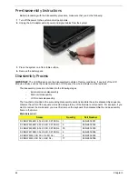
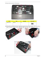
Screw List
Step
Screw
Quantity
Part No.
LCD Module
M2.5*8
2
86.N2802.003
LCD Module
M2.5*8
4
86.N2802.003
Upper Cover
M2.5*8
11
86.N2802.003
Upper Cover
M2.5*8
9
86.N2802.003
Power Board
M2*3
2
86.N2802.006
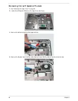
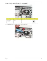
Left Speaker Module
M2*3
1
86.N2802.006
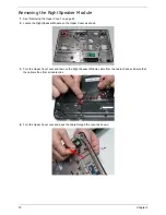
Right Speaker Module
M2*3
1
86.N2802.006
TouchPad Bracket
M2*3
2
86.N2802.006
Mainboard
M2.5*4
1
86.N2802.001
Thermal Module
M1.98*3.0
4
86.N2802.004
CPU Fan
M2*3
3
86.N2802.006
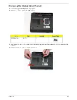
Remove
Mainboard
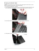
Remove
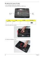
Switch Cover
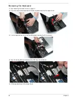
Remove
Keyboard
Remove
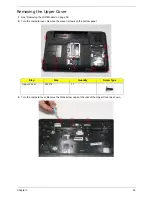
Upper Cover
Remove
LCD Module
Remove
Power Board
Remove External
Modules before
proceeding
Remove
TouchPad
Bracket
Upper
Cover
Lower
Cover
Remove
Left Speaker
Module
Remove
CPU
Remove
RTC Battery
Remove
Thermal Module
Remove
Right Speaker
Module
Remove
CPU Fan
Summary of Contents for AS7315-302G25Mn
Page 6: ...VI ...
Page 10: ...X Table of Contents ...
Page 13: ...Chapter 1 3 System Block Diagram ...
Page 30: ...20 Chapter 1 ...
Page 52: ...42 Chapter 2 ...
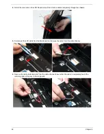
Page 74: ...64 Chapter 3 4 Disconnect the following four cables from the Mainboard A B C D ...
Page 87: ...Chapter 3 77 4 Using both hands lift the Thermal Module clear of the Mainboard ...
Page 89: ...Chapter 3 79 4 Lift the CPU Fan clear of the Mainboard as shown ...
Page 95: ...Chapter 3 85 5 Lift the LCD Panel clear of the module ...
Page 103: ...Chapter 3 93 9 The Antennas and cables appear as shown when correctly installed ...
Page 108: ...98 Chapter 3 2 Replace the four screws and screw caps provided ...
Page 113: ...Chapter 3 103 5 Replace the FFC and press down as indicated to secure it to the Upper Cover ...
Page 124: ...114 Chapter 3 17 Replace the two screws securing the LCD Module to the Lower Cover ...
Page 132: ...122 Chapter 3 ...
Page 164: ...154 Chapter 6 Rear Assembly No Description Acer P N 1 HDD Cover 2 3 RAM Cover 4 5 1 2 3 4 5 ...
Page 174: ...Appendix A 164 Model Definition and Configuration Appendix A ...
Page 196: ...186 Appendix C ...
Page 200: ...190 ...