


V
Preface
Before using this information and the product it supports, please read the following general information.
1.
This Service Guide provides you with all technical information relating to the BASIC CONFIGURATION
decided for Acer's "global" product offering. To better fit local market requirements and enhance product
competitiveness, your regional office MAY have decided to extend the functionality of a machine (e.g.
add-on card, modem, or extra memory capability). These LOCALIZED FEATURES will NOT be covered
in this generic service guide. In such cases, please contact your regional offices or the responsible
personnel/channel to provide you with further technical details.
2.
Please note WHEN ORDERING FRU PARTS, that you should check the most up-to-date information
available on your regional web or channel. If, for whatever reason, a part number change is made, it will
not be noted in the printed Service Guide. For ACER-AUTHORIZED SERVICE PROVIDERS, your Acer
office may have a DIFFERENT part number code to those given in the FRU list of this printed Service
Guide. You MUST use the list provided by your regional Acer office to order FRU parts for repair and
service of customer machines.
Summary of Contents for AS7315-302G25Mn
Page 6: ...VI ...
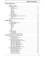
Page 10: ...X Table of Contents ...
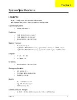
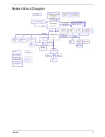
Page 13: ...Chapter 1 3 System Block Diagram ...
Page 30: ...20 Chapter 1 ...
Page 52: ...42 Chapter 2 ...
Page 74: ...64 Chapter 3 4 Disconnect the following four cables from the Mainboard A B C D ...
Page 87: ...Chapter 3 77 4 Using both hands lift the Thermal Module clear of the Mainboard ...
Page 89: ...Chapter 3 79 4 Lift the CPU Fan clear of the Mainboard as shown ...
Page 95: ...Chapter 3 85 5 Lift the LCD Panel clear of the module ...
Page 103: ...Chapter 3 93 9 The Antennas and cables appear as shown when correctly installed ...
Page 108: ...98 Chapter 3 2 Replace the four screws and screw caps provided ...
Page 113: ...Chapter 3 103 5 Replace the FFC and press down as indicated to secure it to the Upper Cover ...
Page 124: ...114 Chapter 3 17 Replace the two screws securing the LCD Module to the Lower Cover ...
Page 132: ...122 Chapter 3 ...
Page 164: ...154 Chapter 6 Rear Assembly No Description Acer P N 1 HDD Cover 2 3 RAM Cover 4 5 1 2 3 4 5 ...
Page 174: ...Appendix A 164 Model Definition and Configuration Appendix A ...
Page 196: ...186 Appendix C ...
Page 200: ...190 ...