


AL722 User’s Manual
Interface for Arm Applications
Before connecting the display to the swivel base support column,
please refer to Fig.1-2.
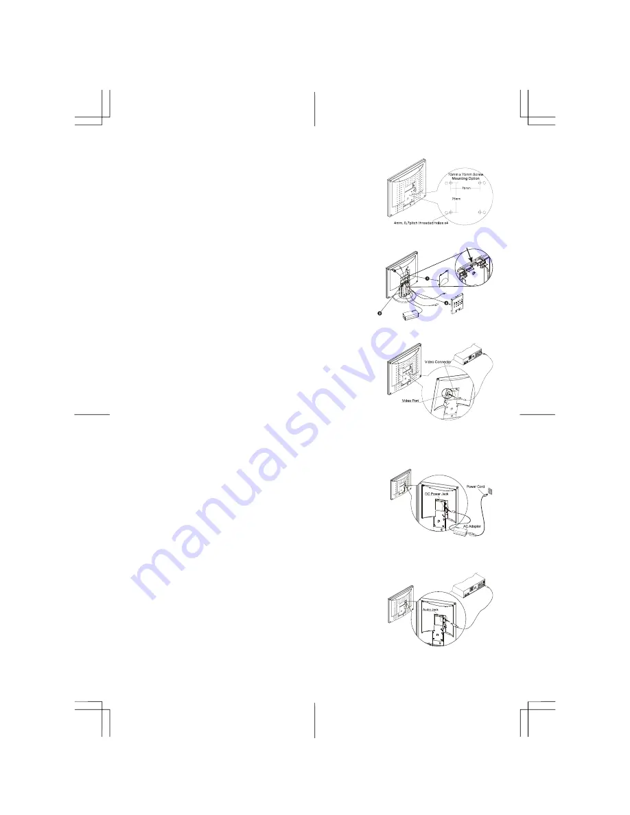
The rear of this LCD display has four integrated 4 mm, 0.7 pitches
threaded nuts, as well as four 5 mm access holes in the plastic
covering as illustrated in Figure 1-3. These specifications meet the
VESA Flat Panel Monitor Physical Mounting Interface Standard
(paragraphs 2.1 and 2.1.3, version 1, dated 13 November 1997)
Figure 1-3
Cable Installation
Please follow these instructions to install the cables. (See Fig. 1-4)
1.
Remove the back panel (1) from the rear of the monitor.
2.
Remove the rear support panel (2) from the swivel base support
column
3.
Place the signal cable, the DC power cable and the audio cable
into their correct respective grooves (3).
Figure 1-4
Connecting the Display to your Computer
1.
Power off your computer.
2.
Connect one end of the signal cable to the LCD Monitor's VGA
port. (See Fig. 1-5)
3.
Connect the other end of the signal cable to the VGA port on your
PC.
4.
Make sure connections are secure
.
Figure 1-5
Attention :
This device must be connected to an off-the-shelf video cable in order to comply with FCC
regulations. A ferrite-core interface cable is included in the LCD Monitor package.
This device will not be in compliance with FCC regulations when a non-ferrite-core video cable is used.
Connecting the AC Power
1.
Connect the power cord to the AC adapter. (See Fig. 1-6)
2.
Connect the AC adapter's DC output connector to the DC Power
Jack of the monitor.
3.
Connect the power cord to an AC power source.
Warning:
We recommand to install a "Surge Protector" device between
the AC Adapter and the electrical wall outlet for adding protection against
power surges to prevent the effects of sudden voltage variations from
reaching the LCD Monitor. Sudden power surges may damage your
monitor.
Figure 1-6
Connecting the Audio Cable
1.
Connect the audio cable to the " LINE OUT " jack on your PC's
audio card or to the front panel's “AUDIO OUT” jack of your CD
ROM drive. (See Fig. 1-7)
2.
Connect the other end of the audio cable to the LCD Monitor's "
LINE IN " jack.
Figure 1-7
3


