


51
Connector Information
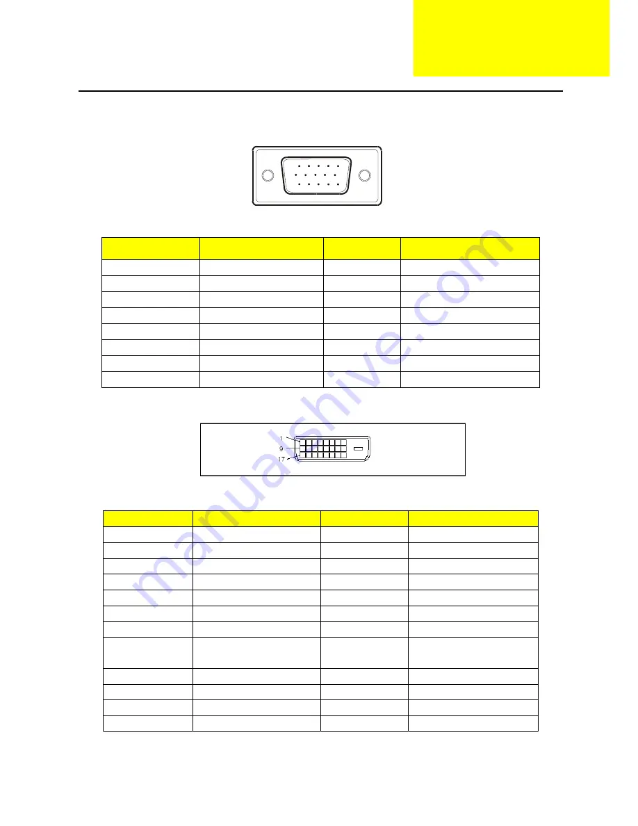
The following figure shows the connector locations on the monitor board:
1
5
6
10
11
15
15 - Pin Color Display Signal Cable(D-sub)
PIN NO.
DESCRIPTION
PI N NO.
DESCRIPTION
1.
Red
9.
NC
2. Green
10.
Ground
3. Blue
11.
Ground
4. Ground
12.
DDC-Serial
Data
5. Ground
13.
H-Sync
6. R-Ground
14.
V-Sync
7. G-Ground
15.
DDC-Serial
Clock
8. B-Ground
24 - Pin Color Display Signal Cable(DVI)
Pin
Meaning
Pin
Meaning
1.
TMDS Data2-
13.
not connected
2.
TMDS Data2+
14.
+5V Power
3.
TMDS Data 2/4 Shield 15.
Ground
4.
not connected
16.
Hot Plug Detect
5.
not connected
17.
TMDS Data0-
6.
DDC Clock
18.
TMDS Data0+
7.
DDC Data
19.
TMDS Data 0/5 Shield
8. Analogue
Vertical
Sync
20. not
connected
9.
TMDS Data1-
21.
not connected
10.
TMDS Data1+
22.
DDC Clock Shield
11.
TMDS Data 1/3 Shield 23.
DDC Clock+
12.
not connected
24.
DDC Clock-
Chapter 5
Summary of Contents for AL1921
Page 19: ...18 Monitor Board Layout ...
Page 24: ...23 Front Bezel Item Description 1 VEDIO UP 2 VEDIO DOWM 3 POWER 4 MENU ENTER 5 AUTO EXIT ...
Page 25: ...24 Rear Bezel Item Description 1 D SUB Cable 2 DVI CABLE 3 AUDIO CABLE 4 AC POWER CORD ...
Page 36: ...35 Step2 Select Bank where is the new firmware ...
Page 38: ...37 Step4 Select the communication Setting Port Name the Port the same your PC COM ...
Page 39: ...38 Step5 Click the ConNect button ...
Page 41: ...40 Step7 ISP is processing ...
Page 42: ...41 Step8 Then you can get the window as follow and Program ok ...


