background image

9

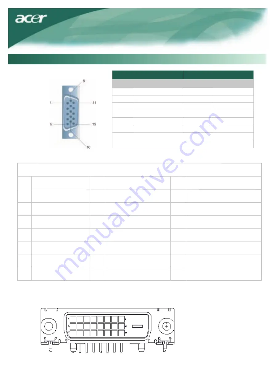
Pin Assignment

Signal

PIN          Description                           PIN          Description
1              Red                                         9              +5V
2             Green                                   10             N.C.
3             Blue                                       11            N.C.
4              N.C.                                       12            DDC_SDA
5             GND                                       13            HSYNC
6              Red_GND                              14           VSYNC.
7             Green_GND                           15            DDC_SCL
8             Blue_GND

Technical Information

Signal

Digital Video Input Connector : DVI – D (option)

1

TX1-

TX0-

2

TX1+

18

Shield (TX2 / TX4)

NC

12

20

5

13

21

6

22

23

8

Hot plug detect

TX2-

TX2+

9

17

10

TX0+

11

Shield (TX0 / TX5)

3

Shield (TX1 / TX3)

19

4

NC

NC

NC

NC

NC

+5V power

DDC-Serial Clock

14

Shield (TXC)

7

15

Ground (+5V)

TXC+

NC

DDC-Serial Data

16

TXC-

24

Summary of Contents for AL1717avw

Page 1: ...iewing Angle Connecting the Devices Switching the Power Adjusting Display Settings External Controls OSD Options OSD Menu Brightness Contrast Tracking Position Color Language Setting Auto Configuration Information Recall General Specifications Technical Information Pin Assignment 9 Standard Timing Table 10 Troubleshooting 1 2 3 3 4 4 4 4 4 4 5 5 5 5 6 6 6 6 6 7 7 7 7 7 8 8 11 OSD Option ...

Page 2: ...fields Noise emissions The requirements included in this label have been developed by TCO Development in co operation with scientists experts users as well as manufacturers all over the world Since the end of the 1980s TCO has been involved in influencing the development of IT equipment in a more user friendly direction Our labelling system started with displays in 1992 and is now requested by use...

Page 3: ...ainability htm Visit www global acer com for further information on our other products and its features and benefits Lamp Disposal IT Equipment Recycling Information LAMP S INSIDE THIS PRODUCT CONTAIN MERCURY AND MUST BE RECYCLED OR DISPOSED OF ACCORDING TO LOCAL STATE OR FEDERAL LAWS FOR MORE INFORMATION CONTACT THE ELECTRONIC INDUSTRIES ALLIANCE AT WWW EIAE ORG FOR LAMP SPECIFIC DISPOSAL INFORMA...

Page 4: ...e AC Cord Spray a non solvent cleaning solution onto a rag and clean the screen gently 2 Do not place the LCD Monitor near a window Exposing the monitor to rain water moisture or sunlight can severely damage it 4 Do not remove the cover or attempt to service this unit by yourself Servicing of any nature should be performed by an authorized technician 5 Operate LCD Monitor in a room with a room tem...

Page 5: ...ther Pull the monitor slightly up and away from the stand Adjusting the Viewing Angle The viewing angle of the monitor ranges from forward 5 to backward 15 Caution Do not force the LCD Monitor over its maximum viewing angle settings as stated above Attempting this will result in damaging the Monitor and Monitor stand Connecting the Devices Please shut down the power of computer and monitor before ...

Page 6: ...e monitor then switch the power on to the computer When you see the LED on the power button go green this indicates the computer is ready for use Allow about 10 seconds for the video signal to appear If you do not see the green light on the power button or a video signal check the connections If OSD is active press to select or adjust OSD options If OSD isactiv e press to exit If OSD is inactive p...

Page 7: ...f there are any vertical stripes seen on the background of the screen this renders them less noticeable by minimizing their size It also changes the size of horizontal screen Position V Position This removes any horizontal distortion and makes the picture clear and sharp H Position This adjusts the horizontal Color Temperature There are three ways of adjusting color temperature WARM Set the color ...

Page 8: ...low user define the OSD appearing period from 10 seconds to 120 seconds Information This shows brief information on the screen Source Change for dual input model Analog and Digital source change DDC CI ON OFF Source Change for analog only model Select turn on or turn off DDC CI function Select turn on or turn off DDC CI function ...

Page 9: ... of Horizontal 160 View Angle of Vertical 160 Power Button ON OFF Control Buttons AUTO MENU Video In VGA DVI D option Sync TTL Plug Play DDC CI 8 Recall Recall to factory default settings Speaker 1Wx2 Power Source 100 240V AC 50 60 Hz 1 5A Power Consumption During Normal Operation 40W Power Consumption During Active off Operation 1W Dimension W_H_D 378 7x395 5x167 6mm base included Weight Net Gros...

Page 10: ...C 7 Green_GND 15 DDC_SCL 8 Blue_GND Technical Information Signal Digital Video Input Connector DVI D option 1 TX1 TX0 2 TX1 18 Shield TX2 TX4 NC 12 20 5 13 21 6 22 23 8 Hot plug detect TX2 TX2 9 17 10 TX0 11 Shield TX0 TX5 3 Shield TX1 TX3 19 4 NC NC NC NC NC 5V power DDC Serial Clock 14 Shield TXC 7 15 Ground 5V TXC NC DDC Serial Data 16 TXC 24 ...

Page 11: ...56 250 60 317 72 188 75 000 60 004 70 069 75 029 60 020 75 025 N N N P P P P N N P P P 25 175 31 500 31 500 36 000 40 000 50 000 49 500 65 000 75 000 78 750 108 000 135 000 N N N P P P P N N P P P 640 350 70Hz 720x400 70Hz 832 624 75Hz 1024 768 60Hz 1024 768 75Hz 800 449 900 449 1152 667 1312 813 1328 804 31 469 31 469 49 728 48 780 60 241 P N N N N 70 086 70 087 74 551 60 001 74 927 P N N N N N 2...

Page 12: ...s still no picture press the Adjustment Control button several times 3 If step 2 doesn t work connect your PC system to another external CRT If your PC system Functions properly with a CRT Monitor but it does not function with the LCD Monitor the output timing of the VGA card may be out of the LCD s synchronous range Please change to an alternative mode listed in the Standard Timing Table or repla...

Reviews: