16
OPERATION INSTRUCTIONS
Press the power button to turn the monitor on or off. The other control buttons are located on the front of the monitor. By
changing these settings, the picture can be adjusted to your personal preferences.
The power cord should be connected.
Connect the video cable from the monitor to the VGA Card.
Press the power button to turn on the monitor, the power indicator will light up.
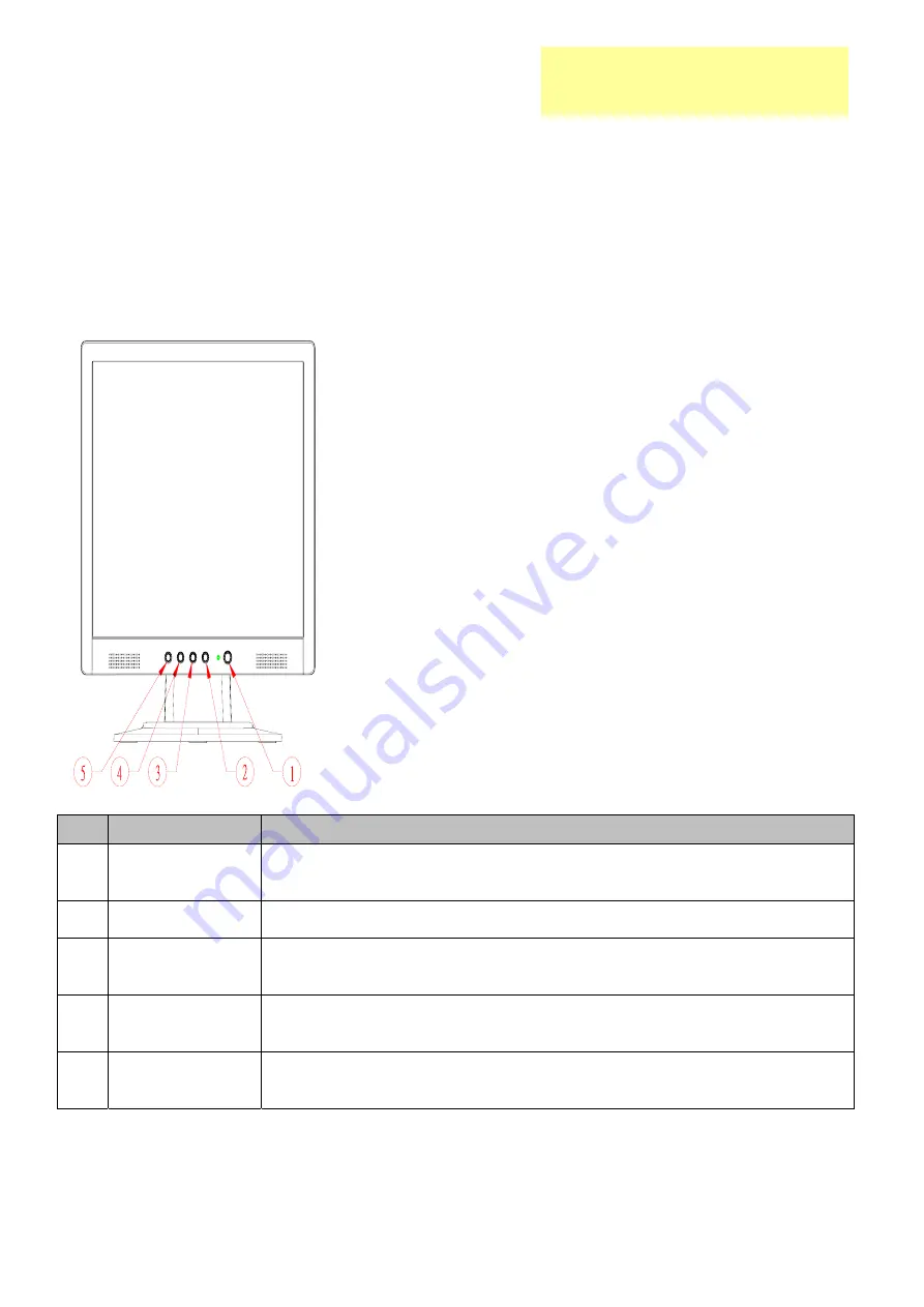
Front Panel Control
No
Symbol
Function
1 Power
key/LED
Press this button to turn the monitor on or off
LED Green – Power On mode
LED Orange – Off mode
2 Menu/Enter
Activate OSD menu when OSD is off or activate/de-activate adjustment function when
OSD is ON or Exit OSD menu when in Volume Adjust OSD status.
3 >
1. Activates the volume control when the OSD is OFF.
2. Navigate through adjustments icons when OSD is ON.
3. Adjust a function when function is activated.
4 <
1. Activates the volume control when the OSD is OFF.
2. Navigate through adjustments icons when OSD is ON.
3. Adjust a function when function is activated.
5 Auto/Exit
1. When OSD menu is in active status, this button will act as EXIT (exit OSD menu)
2. When OSD menu is in off status, press this button for 2seconds to activate the “Auto
Adjustment” which is used to set the H.Pos., V Pos., Clock and Phase.
Chapter 2
Summary of Contents for AL1713bm
Page 13: ...12 MONITOR INTERFACE BOARD PCB LAYOUT ...
Page 15: ...14 FRONT BEZEL ITEM DESCRIPTION 1 Power Tack Switch 2 Menu Enter 3 Up 4 Down 5 Auto Exit ...
Page 26: ...25 Front Bezel 1 Button 1 Indicator 1 Hinge Cover ...
Page 39: ...38 SHEMATIC DIAGRAM Keypad Diagram Chapter 7 ...
Page 40: ...39 Interface Board Schematic ...
Page 41: ...40 ...
Page 42: ...41 ...
Page 43: ...42 ...
Page 44: ...43 ...
Page 45: ...44 ...
Page 46: ...45 POW INV Board Schematic ...
Page 47: ...46 ...


