


AcerPower 2100 User’s Guide
1-12
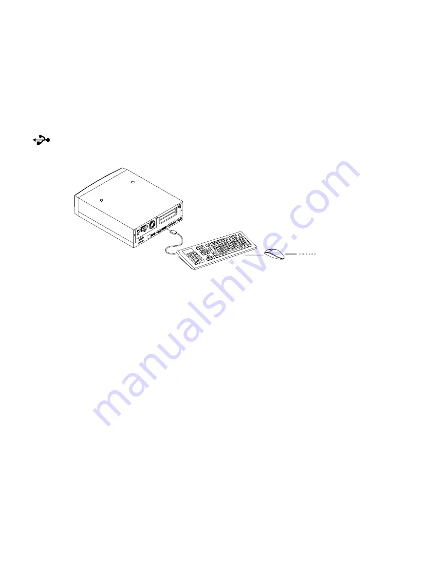
1.3.9
Connecting USB Devices (Optional)
The USB ports on the rear panel enable the system to support additional serial
devices without using up your system resources.
To connect a USB device, simply plug the device cable into a USB port marked
on the rear panel. See the following figure:
Figure 1-11 Connecting USB Devices
Most USB devices have a built-in USB port which allows you to daisy-chain other
devices.


