Accutone A20 OMEGA User Manual & Installation Manual Download Page 4

part a. getting comfortable.

Hooking all the parts together!

A.2

Hooking all the parts together!

A.2

5

4

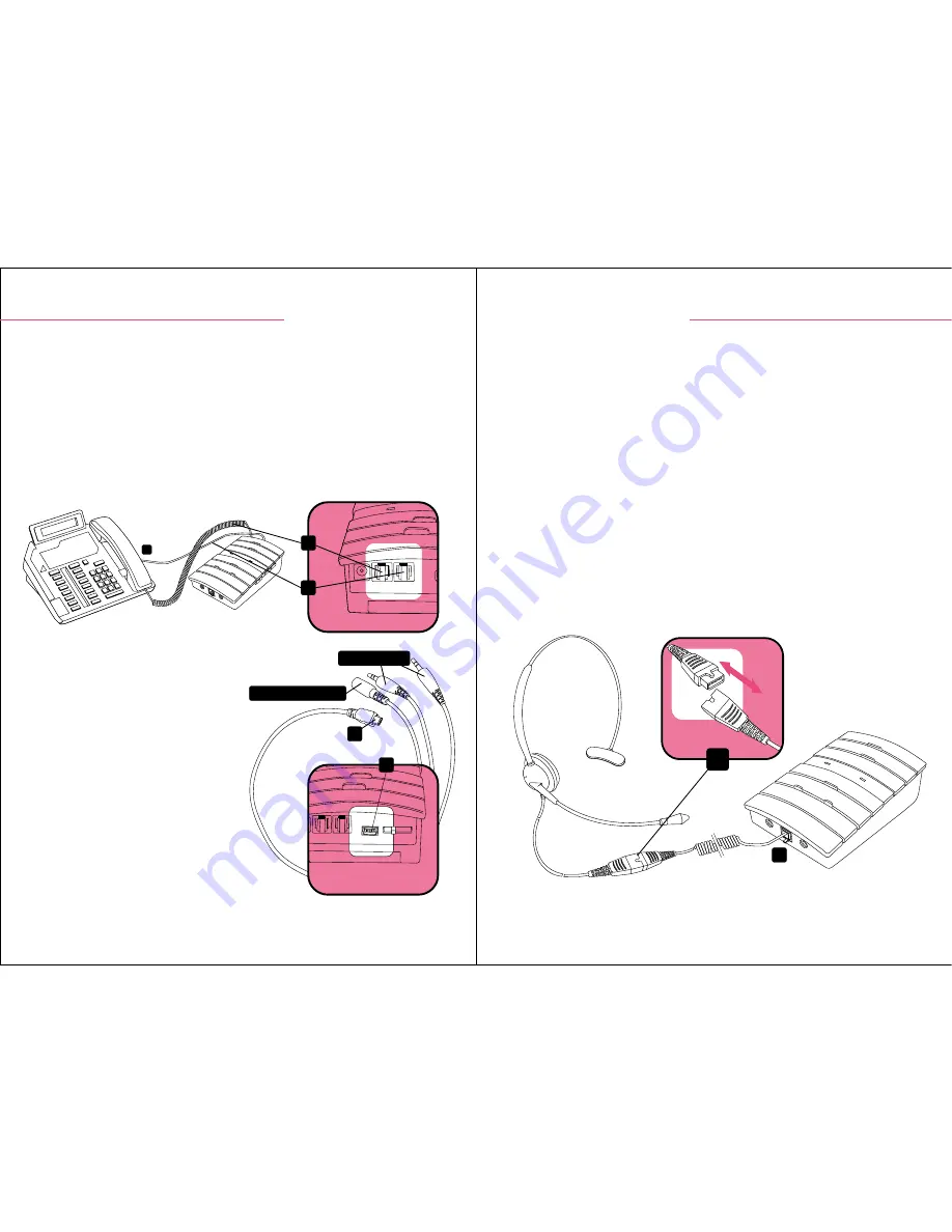
A.2.1 Connect to Telephone

Unplug the handset cord from your telephone base unit and insert it to the 

Modular Jack for Telephone Handset (2)

. Use the phone cord provided 

with  RJ-11 modular  plug  on  both  ends  to  connect  the  control  unit  to  your 
telephone. Plug one end of the cord to your base unit 

(A)

 and the other end 

to the 

Modular Jack for Input from Telephone Unit (3)

 on the back of the 

unit. 

A.2.3 Connect to Telephone Headset

The  A20  Omega  Telephone  Amplifier  provides  the  choice  of  using  any 
Accutone Telephone Headsets equipped with a RJ-11 Modular Plug (except 
TM1200) according to your preference. 

On all Accutone Telephone Headsets pairable to an amplifier, they should be 
equipped with a 

Quick Disconnecting Cable (QD)

. This special feature is 

designed for users who are always on the move. Simply unplug the cable as 
shown below when you need to leave your desk, and plug it together again 
to continue using the unit. 

Plug in the telephone headset to the 

RJ-11


Modular Jack for Telephone 

Headset (16)

 on the front panel of the A20 Omega amplifier. 

16

QD

A

2

3

part a. getting comfortable.

connection & preparations.

connection & preparations.

A.2.2 Connect to Computer

T h e   A 2 0   O m e g a   s u p p o r t s  
connection to both PC soundcard as 
well as most recording devices in the 
market.  Comes  together  with  the 
amplifier is a

 Soundcard/Recording 

-Jack  cable  (J)

  which  connects  to 

the 

PC/Recording  Machine  Jack 

(5)

. Connect the cable, and plug the 

plugs  as  illustrated  to  the  respective 
jack  in  your  soundcard  or  use  the 
recording  jack  for  plugging  your 
recording machine.

5

J

to soundcard

to recording machine

Summary of Contents for A20 OMEGA

Page 1: ...llation guide www accutone com Printed in Hong Kong AASA20 OmegaR2007JUN Copyright 2007 Accutone Technologies Limited All rights reserved Do not copy or re distribute any contents Accutone and the log...

Page 2: ...duction Thank you for purchasing the Accutone A20 Omega Telephone Amplifier This unit is designed to be paired with an Accutone telephone headset which you can find more information from your distribu...

Page 3: ...ephone Configuration Switch Mute Switch Power On Off Switch Microphone Volume Control Slide Switch Muting LED Indicator Reception Volume Control Slide Switch Telephone PC Selection Switch Online LED I...

Page 4: ...o an amplifier they should be equipped with a Quick Disconnecting Cable QD This special feature is designed for users who are always on the move Simply unplug the cable as shown below when you need to...

Page 5: ...9V DC and current is 500mA but we recommend you contact your local dealer for information A 2 6 Headset Hanger Components Along with your A20 Omega amplifier you should be able to find the following...

Page 6: ...t for tidiness and space saving A 2 9 Hanger Installation Part 3 The final step is to place the assembled pieces II III on top of the metal piece I which should already be fastened to the bottom of th...

Page 7: ...andset Application The Headset Handset Application Switch 17 is for you to choose between using the handset of your telephone base unit or the telephone headset provided B I 3 Telephone PC Mode Select...

Page 8: ...ifferent pin configuration users have to pair the amplifier to the telephone model before it can operate effectively The Telephone Configuration Switch 7 at the side panel allows you to select the pro...

Page 9: ...til the desired level is reached The person talking to you at the other end should be able to tell you when the optimum sound and tone level is reached B 1 6 Reception Volume The Reception Volume Cont...

Page 10: ...Volume Gain Controller 18 are designed for Setup Technicians to adjust the transmission and reception level if both Reception Volume Transmission Volume are not enough after fine tuned in the step B 1...

Page 11: ...und The other end cannot hear me well no matter which mic setting I chose B 2 Troubleshooting First Time Installation problem items to check troubleshooting Make sure all the cables are properly hooke...

Page 12: ...able protection against harmful interference in a residential installation This equipment generates uses and can radiate radio frequency energy and if not installed and used in accordance with the ins...

Reviews: