Accurex XRV-25-5I Series Installation, Operation And Maintenance Manual Download Page 29

Packaged Rooftop Ventilator

29

Maintenance Procedures:

Lubrication 

- Check all moving components for 

proper lubrication. Apply lubricant where required. 
Any components showing excessive wear should be 
replaced to maintain the integrity of the unit and ensure 
proper operation.

Dampers

 - Check all dampers to ensure they open and 

close properly and without binding. Backdraft dampers 
can be checked by hand to determine if blades open 
and close freely. Apply power to motorized dampers to 
ensure the actuator opens and closes the damper as 
designed.

Gas Furnace 

- Maintain furnace in accordance with 

instructions in the Indirect Gas-Fired Heat IOM shipped 
with this unit.

Fan Motors 

- Motor maintenance is generally limited 

to cleaning and lubrication. Cleaning should be limited 
to exterior surfaces only. Removing dust and grease 
buildup on the motor housing assists proper cooling. 
Never wash-down the motor with high pressure 
spray. Greasing of motors is only intended when 
fittings are provided. Fan motors typically have two 
grease fittings. Each motor manufacturer has different 
lubrication schedules for different models. Go to the 
motor manufacturer’s website and download their 
maintenance requirements. 

Do not over-lubricate 

motors or use an incompatible grease.

 Many 

fractional motors are permanently lubricated for life and 
require no further lubrication.

Fan Wheel and Fasteners 

- Wheels require very little 

attention when moving clean air. Occasionally oil and 
dust may accumulate on the wheel causing imbalance. 
When this occurs, the wheel and housing should be 
cleaned to assure smooth and safe operation. Inspect 
fan impeller and housing for fatigue, corrosion, or wear.

Routinely check all fasteners, set screws and locking 
collars on the fan, bearings, drive, motor base and 
accessories for tightness. A proper maintenance 
program will help preserve the performance and 
reliability designed into the fan.

Internal Filter Maintenance

 - The unit will typically be 

provided with 2-inch thick pleated paper filters in the 
airstream. These filters should be checked according 
to a routine maintenance schedule and replaced as 
necessary to ensure proper airflow through the unit. 
Replacement filters shall be of same performance and 
quality as factory installed filters. Filter must be pleated 
design with integral metal grid. Two acceptable filter 
replacements are Aerostat Series 400 or Farr 30/30®.

Filters upstream of the coil should be checked regularly. 
If the filters are dirty, they should be cleaned or 
replaced. It is important the filters stay clean to maintain 
desired airflow. 

WARNING

REFER TO GENERAL SAFETY INFORMATION

Do not operate this unit without the filters and 
birdscreen installed. They prevent the entry of foreign 
objects such as leaves, birds, etc.

Do not remove access panels or other unit 
components while standing on a ladder or other 
unsteady base. Access panels and unit components 
are heavy and serious injury may occur.

Coil Maintenance

- Coils must be cleaned to maintain 

maximum performance. Check coils once per year 
under normal operating conditions and if dirty, brush 
or vacuum clean. Soiled fins reduce the capacity of the 
coil, demand more energy from the fan and create an 
environment for odor and bacteria to grow and spread 
through the conditioned zone. High pressure water 
(700 psi or less) may be used to clean coils with a fin 
thickness over 0.0095 inches thick. 

TEST THE SPRAY 

PRESSURE

 over a small corner of the coil to determine 

if the fins will withstand the spray pressure.
For coils with fragile fins or high fin density, foaming 
chemical sprays and washes are available. Many coil 
cleaners use harsh chemicals, so they must be used 
with caution by qualified personnel only. Care must be 
taken not to damage the coils, including the fins, while 
cleaning. 

Caution: Fin edges are sharp!

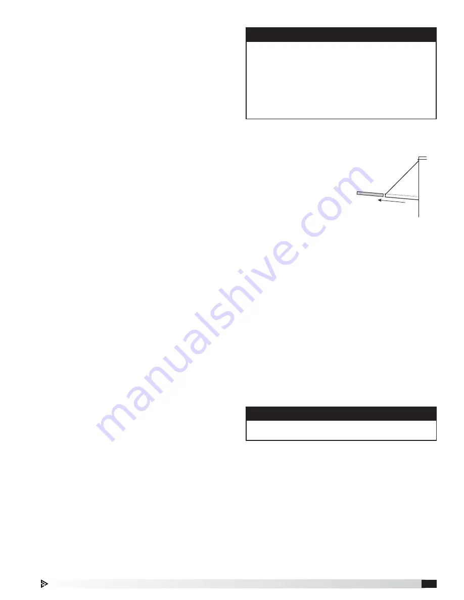
External Filter Maintenance

- Aluminum mesh, 2-inch 

thick filters are located in the supply weatherhood (if 
the weatherhood option was purchased). These filters 
should be checked and 
cleaned on a regular basis 
for best efficiency. The 
frequency of cleaning 
depends upon the 
cleanliness of the incoming 
air. These filters should be 
cleaned by rinsing with 
a mild detergent in warm 
water prior to start-up.

Filter

Outdoor Air Intake Hood  

Mesh Filter Access

WARNING

Biological hazard. May cause disease. Cleaning 
should be performed by qualified personnel.

Drain pans in any air conditioning unit will have some 
moisture in them, therefore, algae and other organisms 
will grow due to airborne spores and bacteria. Periodic 
cleaning is necessary to prevent this buildup from 
plugging the drain and causing the drain pan to 
overflow. Inspect twice a year to avoid the possibility 
of overflow. Also, drain pans should be kept clean to 
prevent the spread of disease. Cleaning should be 
performed by qualified personnel.

Summary of Contents for XRV-25-5I Series

Page 1: ...en servicing the unit the internal components may be hot enough to cause pain or injury Allow time for cooling before servicing Only quali ed personnel should install and maintain this system Personne...

Page 2: ...VFD Sequence 13 OA and Recirc Air Damper Sequence 13 Exhaust Fan Only Power 13 Vapor Tight Lights 13 EC Condenser Fans 14 Airflow Monitor 14 Dirty Filter Sensor 15 Microprocessor Control 15 Unoccupie...

Page 3: ...ove any accumulations of dirt water ice or snow and wipe dry before moving to indoor storage To avoid condensation allow cold parts to reach room temperature Leave coverings loose to permit air circul...

Page 4: ...illed water coil Units with packaged DX are shipped fully charged with refrigerant and are ready for operation upon arrival Heating There are three different optional heat sources that can be ordered...

Page 5: ...denser Coils optional Outdoor Air Damper Coils optional Recirculating Damper Main Control Center Furnace Vest Plate and Furnace Control Center optional Outdoor Air Filters Weatherhood Filters metal me...

Page 6: ...ce Optional Electric Heater 4 Electrical 5 Supply Blower 6 Coil 7 Filters Unit Size Nominal tonnage tons Height H Width W Length L Intake A Condensing Section B Nominal weight lbs Outdoor Intake Suppl...

Page 7: ...nit Weights Dimensions section of this manual 3 Unit must be lifted by all lifting lugs provided at top of unit 4 Spreader bars must span the unit to prevent damage to the cabinet by the lift cables 5...

Page 8: ...Shim the curb as required to level Install gasketing on top surface of curb provided by others 3 Install Ductwork Installation of all ducts should be done in accordance with SMACNA and AMCA guidelines...

Page 9: ...There are three penetrations into the cabinet that are required one for high voltage supply wiring one for low voltage control wiring and one for either gas supply or high voltage supply wiring for a...

Page 10: ...aking the weld between coil connection and header 2 Connect the water supply to the bottom connection on the air leaving side and the water return to the top connection on the air entering side Connec...

Page 11: ...ater disconnect and must be compatible with the ratings on the nameplate supply power voltage phase and amperage Consult ANSI NFPA 70 and CSA C22 1 for proper conductor sizing Provide the Opening s fo...

Page 12: ...ontroller Optional Indirect Gas Fired Furnace Note In some models two furnaces are installed to provide greater output When two furnaces are installed they are in parallel and both will operate at the...

Page 13: ...ain room air temp at a desired set point Optional 0 10 VDC by others to VFD Supply fan is modulated by a 0 10 VDC eld provided by others Component Operation Exhaust Fan VFD Sequence Optional Building...

Page 14: ...actual cubic feet per minute CFM or actual liters per second LPS on a 16 character LCD display Two con gurable analog outputs for transmitting outdoor and or exhaust air ow rate outdoor air temperatur...

Page 15: ...or relative humidity sensor the unit can cycle on to maintain unoccupied room set points if there is a call for unoccupied heating cooling or dehumidi cation During the unoccupied mode the supply and...

Page 16: ...ble and is located on the side of the evaporator coil and can be accessed through the coil access panel 13 Evaporative Coil 14 Low Limit Pressure Switch The switch is installed on the suction line and...

Page 17: ...is below 40 F Do not short cycle the compressor Allow 5 minutes between on cycles to prevent compressor damage DX system is charged with refrigerant Start up must be performed by EPA Certified Technic...

Page 18: ...wer supplied to it 24 hours prior to start up If start up is scheduled in 24 hours unlock the disconnect power and energize unit Compressor shipping brackets are removed if provided SPECIAL TOOLS REQU...

Page 19: ...r Air Temperature Deg F Outdoor Air Relative Humidity RH Return Air Temperature Deg F Return Air Relative Humidity RH Compressor 1 Compressor 2 Compressor 3 Compressor 4 L1 Amps Amps Amps Amps L2 Amps...

Page 20: ...vation cannot locate the source of vibration a quali ed technician using vibration analysis equipment should be consulted Generally fan vibration and noise is transmitted to other parts of the buildin...

Page 21: ...unit using the power disconnect s a Recycling of the power resets the manual override values that were set during the calibration Air ow Monitor For additional information on how to navigate through t...

Page 22: ...as a voltage spike occurs the VFD will go into alarm and will not reset until a hard restart is performed See the unit speci c manufacturer s manual supplied with the unit VFDs are located in the mai...

Page 23: ...er motor System static pressure too high Improve ductwork to eliminate losses using good duct practices Blower speed too low Check maximum motor RPM and compare with catalog data Verify that external...

Page 24: ...or reason and repair Replace fuse after correcting problem Low line voltage Check line voltage If more than 10 from compressor marking correcting is necessary Compressor motor protector open Motor the...

Page 25: ...f compressor is hot allow compressor to cool for two hours Recheck for open circuit Improper refrigerant charge Check subcooling Improperly wired Review wiring schematics Loose wiring Check all connec...

Page 26: ...Check subcooling Remove excess refrigerant Non condensable in system Remove non condensable from system Dirty condenser coil Clean condenser coil Condenser fan not running or running backwards Check e...

Page 27: ...back Check thermal expansion valve setting Check for refrigerant overcharge Check crankcase heater operation Reheat ush cycle inadequate Contact factory Not enough cooling or lack of cooling Refriger...

Page 28: ...ebris in the air which can be drawn into the lters and the coils they should be checked more frequently If the system is being used for only a few hours per day the frequency may be reduced Use the ma...

Page 29: ...integral metal grid Two acceptable lter replacements are Aerostat Series 400 or Farr 30 30 Filters upstream of the coil should be checked regularly If the lters are dirty they should be cleaned or re...

Page 30: ...V 45 300 14 8 23 3 38 1 44 1 6 6 6 400 6 6 6 500 14 9 23 6 25 2 57 1 6 6 6 B A C D 500MBH 300 400MBH A B C D 200 300MBH 100 150MBH C A B D C A B D COMBUSTION AIR INLET EXHAUST OUTLET IG FURNACE ACCESS...

Page 31: ...5 12 5S 3550 XRV 25 15I 3775 XRV 25 15D 3775 XRV 25 15S 3775 XRV 45 15I 4100 XRV 45 15D 4100 XRV 45 15S 4100 XRV 45 17 5I 4650 XRV 45 17 5D 4650 XRV 45 17 5S 4650 XRV 45 20I 5300 XRV 45 20D 5300 XRV 4...

Page 32: ...______________________________________ _________________________________________________ Date ___________________Time _____________ AM PM Notes ___________________________________________ ____________...

Reviews: